
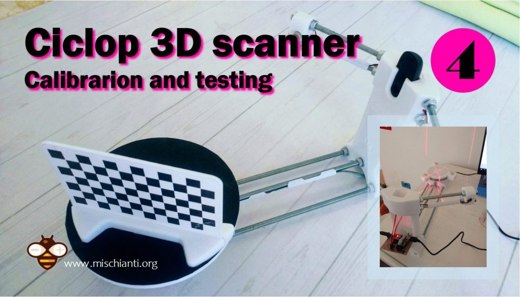
Ciclop 3D scanner: components testing and calibration – 4
Now the last part of the tutorial on “How to build a Ciclop 3D scanner”, in the previous articles we have build the components and assembly they, now we start calibration and testing.
Testing the PCB
First we are going to test the PCB created in the previous articles.
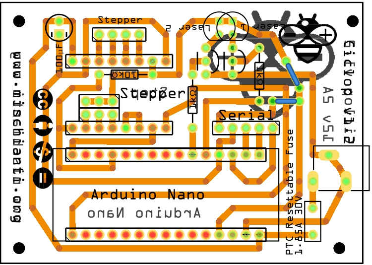
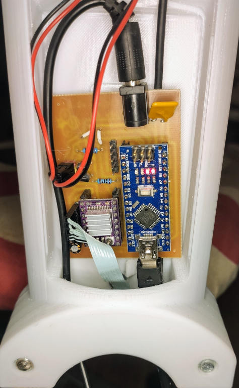
Here the new board active and mounted.
You can order the PCB at PCBWay for few dollars here
Ciclop 3D scanner board v1.2 PCBWay

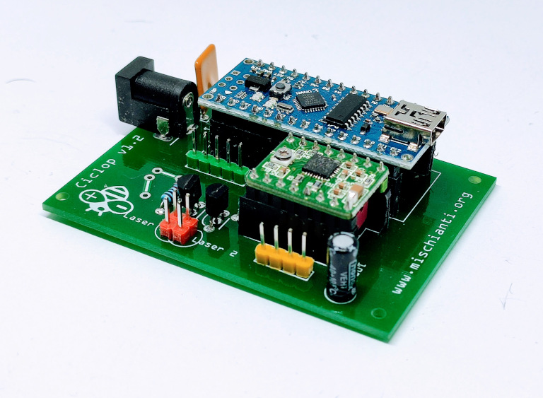
Testing the board v1.0 v1.2 with a simple sketch
First I test all without camera, and It’s work well.
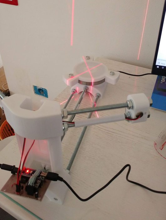
You can use this sketch to check laser and stepper.
#include "Arduino.h"

#define STEPPER 9
#define STEPPER_STEP 12

#define STEPPER_MICROSENCOND (unsigned long)80000*8

void setup()
{

	Serial.begin(9600);
	pinMode(STEPPER, OUTPUT);
	digitalWrite(STEPPER, LOW);
	Serial.println("LASER 1 ON");
	pinMode(2, OUTPUT);
	digitalWrite(2, HIGH);
	Serial.println("LASER 2 ON");
	pinMode(3, OUTPUT);
	digitalWrite(3, HIGH);

	Serial.println("START STEPPER ON LOOP");

}

void loop()
{
	  digitalWrite(STEPPER_STEP, HIGH);
	  delayMicroseconds(STEPPER_MICROSENCOND);
	  digitalWrite(STEPPER_STEP, LOW);
	  delayMicroseconds(STEPPER_MICROSENCOND);
}
Firmware and Software
You can download the firmware to upload to the Arduino from here
As described in the guide the camera is a Logitech C270 HD webcam.
You can find supported web cam here AliExpressLogitech c270 support and drivers
You can find Horus software here.

if you have some trouble to download you can go here.
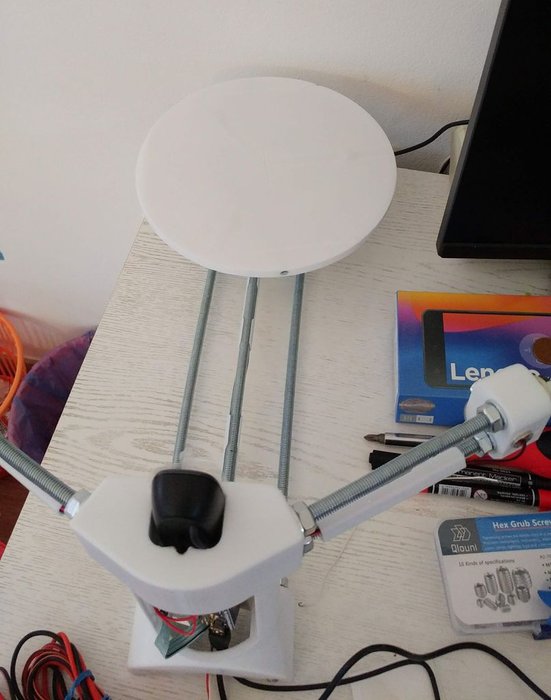
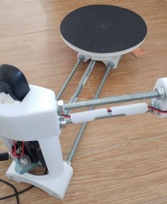
Check the assembling process
Than I add camera, fix board and add a black paper on the top of platform.
Calibration
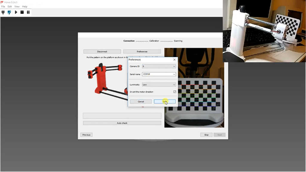
There are a lot of video about calibration, this step is very simple, you can only follow the widzard proposed.
I realize this minimal video with my new Ciclop.
First Mandarin Test
Here the complete guide to scanning process.
In this video I only scan the object, but to have a good image you must do some post processing with a software like MeshLab.
There is a post-processing manual
Thanks
Now start scan all.
- Ciclop 3D scanner: component printing and assembly
- Ciclop 3D scanner: production and assembly of the control PCB
- Ciclop 3D scanner: assembling electronic and wiring
- Ciclop 3D scanner: componens testing and calibration


laser trangulation calibration has failled i can’t do this correct why
Hi Frans,
I am sorry to hear you are having trouble. The ‘Laser Triangulation’ failure is usually caused by the camera not being able to detect the laser line correctly on the pattern. Here are the most common things to check:
Let me know if any of these solve the issue!
Bye Renzo