PCF8574 i2c digital I/O expander: Arduino, esp8266 and esp32, basic I/O and interrupt – Part 1

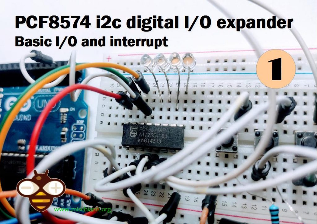
Key features of PCF8574 I2C I/O expansion
- 8 bi-directional data lines
- Loop-thru feature allows expansion of up to 8 modules / 64 data lines
- I2C interface with jumper adjustable addresses
- Interrupt output capability
- 3.3V and 5V compatible.
A common requirement when working with MCUs is the need to add more digital I/O than the device supports natively. The PCF8574 is one of the more popular methods of adding lines as it uses the I2C bus that requires only 2 lines on the MCU. It provides 8 additional digital I/O lines, which are easily expandable up to 64.
I2C Interface
The module has an easy-to-use I2C interface that can be configured to use any one of eight different I2C addresses if you want to use multiple modules in the same system or if you run into an address conflict with another device.
There are three address jumps (A0-A2) that determine which I2C address to use. As shipped, these jumpers are all set to the ‘-‘ side, which is ground or LOW, as shown in the picture. The ‘+’ side is Vcc or HIGH.
I/O Functionality
The I/O is defined as quasi-bidirectional. A quasi-bidirectional I/O is either an input or output port without using a direction control register. When set as inputs, the pins act as normal inputs do. When set as outputs, the PCF8574 device drives the outputs LOW with up to 25mA sink capability, but when driving the outputs HIGH, they are just pulled up high with a weak internal pull-up. That enables an external device to overpower the pin and drive it LOW.
The device powers up with the 8 data lines all set as inputs.
When using the pins as inputs, the pins are set to HIGH by the MCU, which turns on a weak 100 uA internal pull-up to Vcc. They will read as HIGH if there is no input or if the pin is being driven HIGH by an external signal but can be driven LOW by an external signal that can easily override the weak pull-up.
If used as outputs, they can be driven LOW by the MCU by writing a LOW to that pin. A strong pull-down is turned on and stays on to keep the pin pulled LOW. If the pin is driven HIGH by the MCU, a strong pull-up is turned on for a short time to pull the pin HIGH quickly, and then the weak 100uA pull-up is turned back on to keep the pin HIGH.
If the pins are set to be outputs and are driven LOW, it is important that an external signal does not also try to drive it HIGH or excessive current may flow and damage the part.
Whenever the internal register is read, the value returned depends on the actual voltage or status of the pin.
The I/O ports are entirely independent of each other, but they are controlled by the same read or write data byte.
Interrupt Output
The interrupt open-drain output pin is active LOW. It is normally pulled HIGH using a pull-up resistor and is driven low by the PCF8574 when any of the inputs change state. This signals the MCU to poll the part to see what is going on. If connecting this pin, enable the internal pull-up resistor on the MCU or add an external pull-up of 10K or so.
If using interrupts with multiple modules, since they are open drain they can be tied together if a single interrupt back to the MCU is desired.
Module Connections
The connections to the module are straightforward.
- Supply 3.3 or 5V power and ground.
- Connect I2C SCL and SDA lines to the same on the MCU.
- If used, connect the INT line to an interrupt input on the MCU and use a pull-up resistor.
I write a library to use i2c pcf8574 IC with Arduino and esp8266.
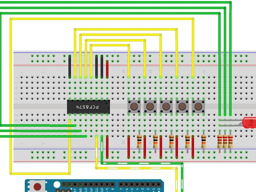
So can read and write digital value with only 2 wires (perfect for ESP-01).
I try to simplify the use of this IC with a minimal set of operations.
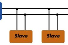
How I2c Works
I2C works with its two wires, the SDA(data line) and SCL(clock line).
Both these lines are open-drain but are pulled up with resistors.
Usually, there is one master and one or multiple slaves on the line, although there can be multiple masters. We’ll talk about that later.
Both masters and slaves can transmit or receive data. Therefore, a device can be in one of these four states: master transmit, master receive, slave transmit, and slave received.
Library
You can find my library here.
To download.
Click the DOWNLOADS button in the top right corner, and rename the uncompressed folder PCF8574.
Check that the PCF8574 folder contains PCF8574.cpp and PCF8574.h.
Place the PCF8574 library folder your /libraries/ folder.
You may need to create the libraries subfolder if its your first library.
Restart the IDE.
IC or Module
You can use a normal IC or module.

You can find the IC on AliExpress

Usage
I try to simplify the use of this IC with a minimal set of operations.
PCF8574P address map 0x20-0x27 PCF8574AP address map 0x38-0x3f
Constructor
On the constructor, you must pass the address of i2c. You can use A0, A1, and A2 pins to change the address, and you can find the address value here (to check the address use this guide I2cScanner)
PCF8574(uint8_t address);
for esp8266, if you want to specify SDA e SCL pin, use this:
PCF8574(uint8_t address, uint8_t sda, uint8_t scl);
For esp32, you can pass directly the TwoWire, so you can choose the secondary i2c channel: [updated 29/04/2019]
// Instantiate Wire for generic use at 400kHz
TwoWire I2Cone = TwoWire(0);
// Instantiate Wire for generic use at 100kHz
TwoWire I2Ctwo = TwoWire(1);

// Set dht12 i2c comunication with second Wire using 21 22 as SDA SCL
DHT12 dht12(&I2Ctwo);
//DHT12 dht12(&I2Ctwo, 21,22);
//DHT12 dht12(&I2Ctwo, 0x5C);
//DHT12 dht12(&I2Ctwo, 0x5C, 21, 22);
Input/Output mode and starting value
You must set input/output mode:
	pcf8574.pinMode(P0, OUTPUT);
	pcf8574.pinMode(P1, INPUT);
	pcf8574.pinMode(P2, INPUT);
You can manage the initial value of various pins: [updated 06/03/2020]
You can define for input if you want to manage an INPUT or INPUT_PULLUP
pcf8574.pinMode(P0, INPUT);
pcf8574.pinMode(P1, INPUT_PULLUP);
And for OUTPUT, you can specify the initial value at the beginning of IC: [updated 06/03/2020]
pcf8574.pinMode(P6, OUTPUT, LOW);
pcf8574.pinMode(P6, OUTPUT, HIGH);
for backward compatibility default value of OUTPUT is HIGH.
then IC, as you can see in the image, have 8 digital input/output:
So to read all analog input in one transmission, you can do (even if I use a 10millis debounce time to prevent too much read from i2c):
	PCF8574::DigitalInput di = PCF8574.digitalReadAll();
	Serial.print("READ VALUE FROM PCF P1: ");
	Serial.print(di.p0);
	Serial.print(" - ");
	Serial.print(di.p1);
	Serial.print(" - ");
	Serial.print(di.p2);
	Serial.print(" - ");
	Serial.println(di.p3);
Low memory
To follow a request (you can see It on issue #5), I created a defined variable to work with a low-memory device. If you uncomment this line on .h file of the library:
// #define PCF8574_LOW_MEMORY
Enable low memory props and gain about 7byte of memory, and you must use the method to read all like so:
   byte di = pcf8574.digitalReadAll();
   Serial.print("READ VALUE FROM PCF: ");
   Serial.println(di, BIN);
where di is a byte like 1110001, so you must do a bitwise operation to get the data, an operation that I already do in the “normal” mode. Here is an example:
   p0 = ((di & bit(0)>0)?HIGH:LOW;
   p1 = ((di & bit(1)>0)?HIGH:LOW;
   p2 = ((di & bit(2)>0)?HIGH:LOW;
   p3 = ((di & bit(3)>0)?HIGH:LOW;
   p4 = ((di & bit(4)>0)?HIGH:LOW;
   p5 = ((di & bit(5)>0)?HIGH:LOW;
   p6 = ((di & bit(6)>0)?HIGH:LOW;
   p7 = ((di & bit(7)>0)?HIGH:LOW;
if you want to read a single input:
int p1Digital = PCF8574.digitalRead(P1); // read P1
[updated 13/03/2020] you can also force reread of value without debouncing
int p1Digital = PCF8574.digitalRead(P1, true); // read P1 without debounce
If you want to write a digital value, you must do the following:
PCF8574.digitalWrite(P1, HIGH);
or:
PCF8574.digitalWrite(P1, LOW);
Interrupt
You can also use interrupt pin: You must initialize the pin and the function to call when an interrupt is raised from PCF8574
// Function interrupt
void keyPressedOnPCF8574();

// Set i2c address
PCF8574 pcf8574(0x39, ARDUINO_UNO_INTERRUPT_PIN, keyPressedOnPCF8574);
Remember, you can’t use Serial or Wire on the interrupt function.
The better way is to set only a variable to read on the loop:
void keyPressedOnPCF8574(){
	// Interrupt called (No Serial no read no wire in this function, and DEBUG disabled on PCF library)
	 keyPressed = true;
}
Low latency
For low latency applications (lesser than 10millis), I added a new define that you could uncomment and activate 1millis latency [updated 06/03/2020].
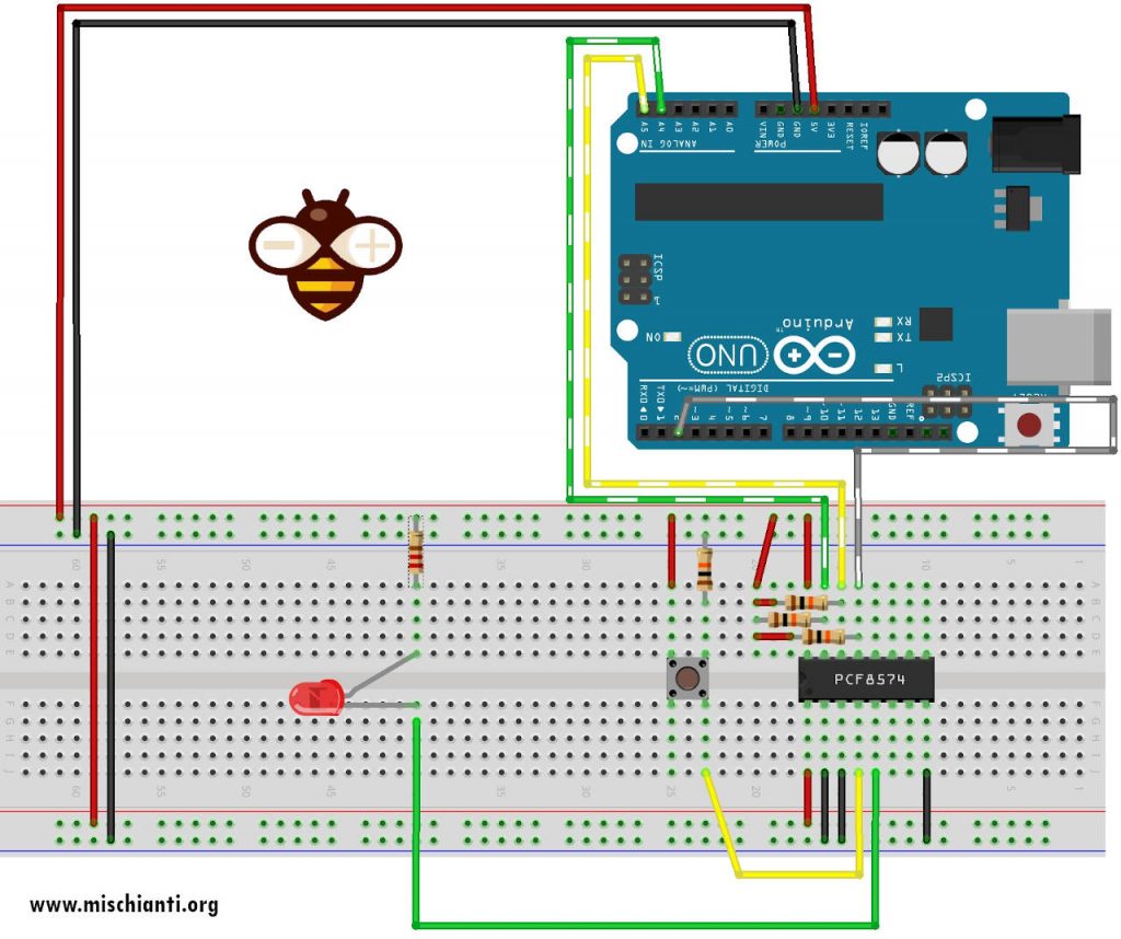
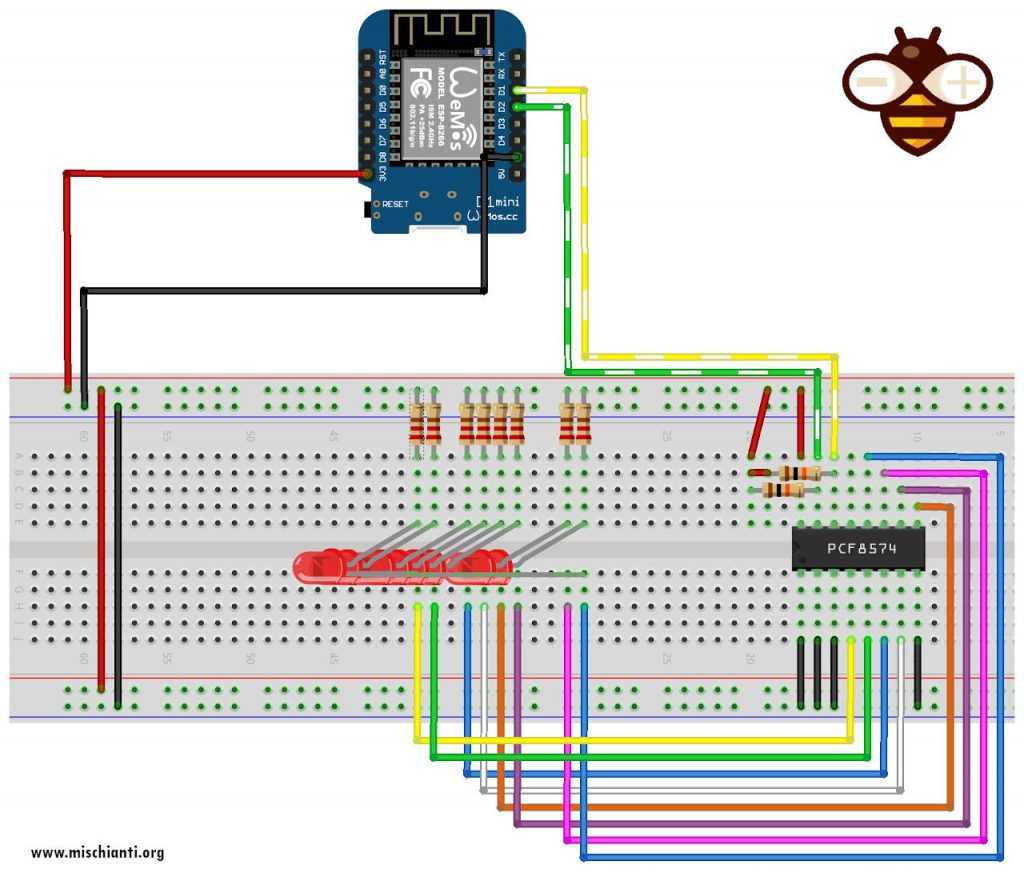
Connections schema

For the examples, I use this wire schema on the breadboard:
Additional examples
In the time peoples help me to create new examples, I’m going to add them here:
Wemos LEDs blink
From japan, nopnop create an example to blink 8 leds sequentially.
/*
 * PCF8574 GPIO Port Expand
 * http://nopnop2002.webcrow.jp/WeMos/WeMos-25.html
 *
 * PCF8574    ----- WeMos
 * A0         ----- GRD
 * A1         ----- GRD
 * A2         ----- GRD
 * VSS        ----- GRD
 * VDD        ----- 5V/3.3V
 * SDA        ----- GPIO_4(PullUp)
 * SCL        ----- GPIO_5(PullUp)
 *
 * P0     ----------------- LED0
 * P1     ----------------- LED1
 * P2     ----------------- LED2
 * P3     ----------------- LED3
 * P4     ----------------- LED4
 * P5     ----------------- LED5
 * P6     ----------------- LED6
 * P7     ----------------- LED7
 *
 */

#include "Arduino.h"
#include "PCF8574.h"  // https://github.com/xreef/PCF8574_library

// Set i2c address
PCF8574 pcf8574(0x20);

void setup()
{
  Serial.begin(9600);

  // Set pinMode to OUTPUT
  for(int i=0;i<8;i++) {
    pcf8574.pinMode(i, OUTPUT);
  }
  pcf8574.begin();
}

void loop()
{
  static int pin = 0;
  pcf8574.digitalWrite(pin, HIGH);
  delay(1000);
  pcf8574.digitalWrite(pin, LOW);
  delay(1000);
  pin++;
  if (pin > 7) pin = 0;
}
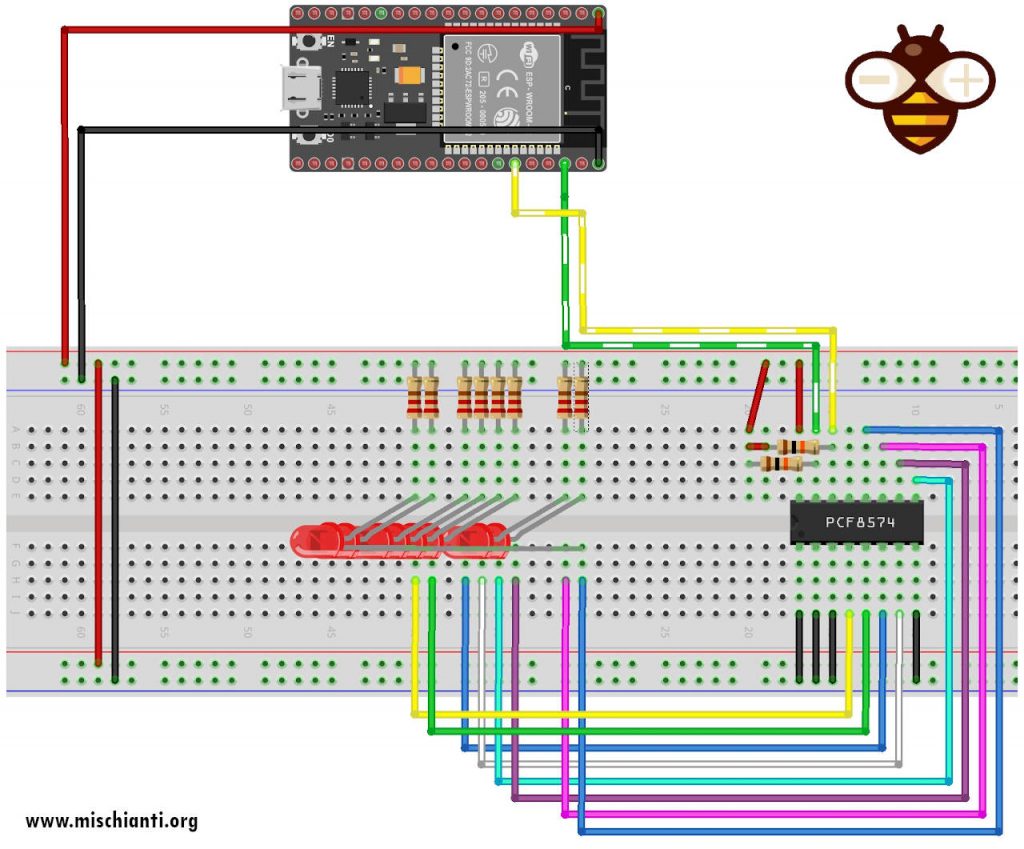
Esp32 LEDs blink using a secondary i2c channel.
Here I create a variant of the example to show how to use the secondary i2c channel of an esp32.
#include "Arduino.h"
/*
 * 	PCF8574 GPIO Port Expand
 *  Blink all led
 *  by Mischianti Renzo <https://mischianti.org>
 *
 *  https://mischianti.org/pcf8574-i2c-digital-i-o-expander-fast-easy-usage/
 *
 *
 * PCF8574    ----- Esp32
 * A0         ----- GRD
 * A1         ----- GRD
 * A2         ----- GRD
 * VSS        ----- GRD
 * VDD        ----- 5V/3.3V
 * SDA        ----- 21
 * SCL        ----- 22
 *
 * P0     ----------------- LED0
 * P1     ----------------- LED1
 * P2     ----------------- LED2
 * P3     ----------------- LED3
 * P4     ----------------- LED4
 * P5     ----------------- LED5
 * P6     ----------------- LED6
 * P7     ----------------- LED7
 *
 */

#include "Arduino.h"
#include "PCF8574.h"  // https://github.com/xreef/PCF8574_library

// Instantiate Wire for generic use at 400kHz
TwoWire I2Cone = TwoWire(0);
// Instantiate Wire for generic use at 100kHz
TwoWire I2Ctwo = TwoWire(1);

// Set i2c address
PCF8574 pcf8574(&I2Ctwo, 0x20);
// PCF8574 pcf8574(&I2Ctwo, 0x20, 21, 22);
// PCF8574(TwoWire *pWire, uint8_t address, uint8_t interruptPin,  void (*interruptFunction)() );
// PCF8574(TwoWire *pWire, uint8_t address, uint8_t sda, uint8_t scl, uint8_t interruptPin,  void (*interruptFunction)());

void setup()
{
  Serial.begin(112560);

  I2Cone.begin(16,17,400000); // SDA pin 16, SCL pin 17, 400kHz frequency

  // Set pinMode to OUTPUT
  for(int i=0;i<8;i++) {
    pcf8574.pinMode(i, OUTPUT);
  }
  pcf8574.begin();
}

void loop()
{
  static int pin = 0;
  pcf8574.digitalWrite(pin, HIGH);
  delay(400);
  pcf8574.digitalWrite(pin, LOW);
  delay(400);
  pin++;
  if (pin > 7) pin = 0;
}
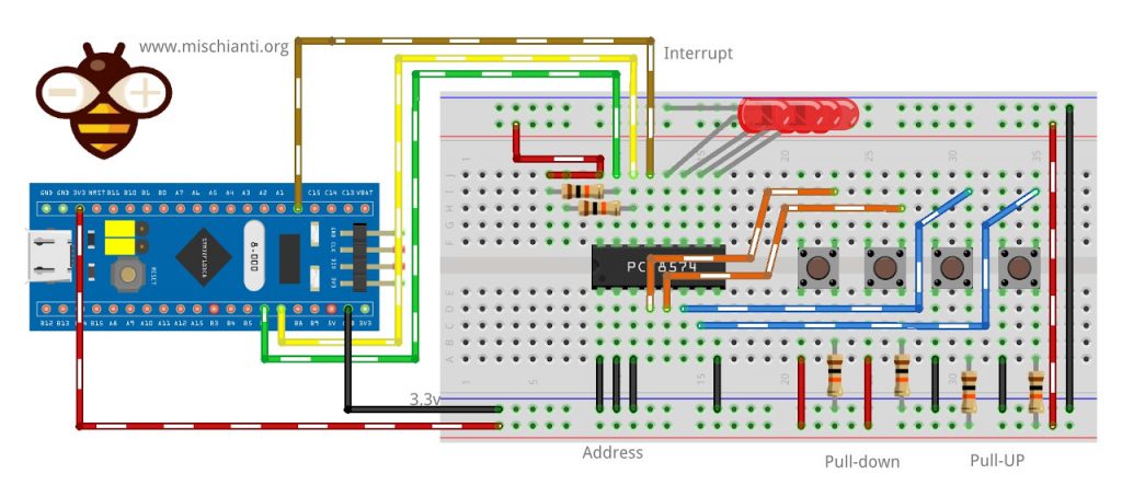
STM32 manage 4 buttons and 4 LEDs at the same time
Use PA1 as an interrupt pin and follow the instruction of the next example.
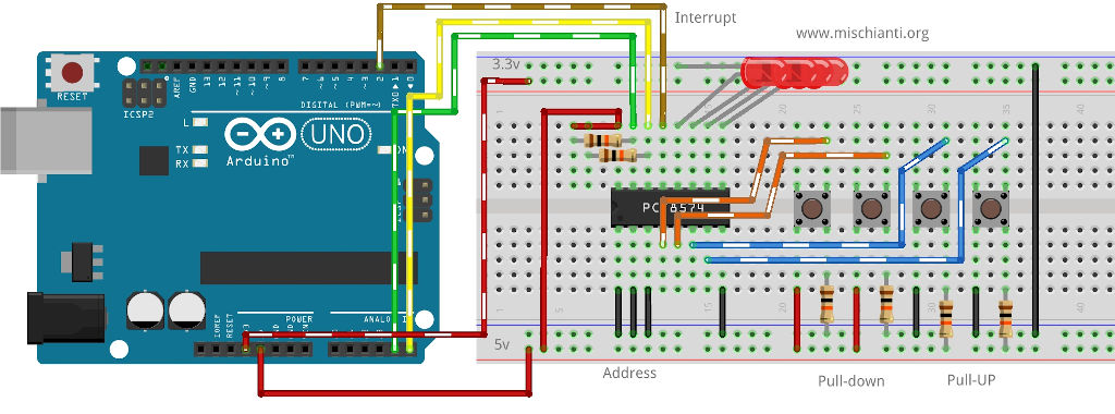
Arduino manages 4 buttons and 4 LEDs at the same time
Here is an example of simultaneous input and output. If you intend to manage the simultaneous pressure of the buttons, the latency must be reduced to 0 or the specific define set. Another way is to use the adjective parameter to true on the digitalRead.
/*
 KeyPressed and leds with interrupt
 by Mischianti Renzo <https://mischianti.org>

  https://www.mischianti.org/pcf8574-i2c-digital-i-o-expander-fast-easy-usage/

*/

#include "Arduino.h"
#include "PCF8574.h"

// For arduino uno only pin 1 and 2 are interrupted
#define ARDUINO_UNO_INTERRUPTED_PIN 2

// Function interrupt
void keyPressedOnPCF8574();

// Set i2c address
PCF8574 pcf8574(0x38, ARDUINO_UNO_INTERRUPTED_PIN, keyPressedOnPCF8574);
unsigned long timeElapsed;
void setup()
{
    Serial.begin(115200);

    pcf8574.pinMode(P0, INPUT_PULLUP);
    pcf8574.pinMode(P1, INPUT_PULLUP);
    pcf8574.pinMode(P2, INPUT);
    pcf8574.pinMode(P3, INPUT);

    pcf8574.pinMode(P7, OUTPUT);
    pcf8574.pinMode(P6, OUTPUT, HIGH);
    pcf8574.pinMode(P5, OUTPUT);
    pcf8574.pinMode(P4, OUTPUT, LOW);

    pcf8574.begin();

    timeElapsed = millis();
}
unsigned long lastSendTime = 0;        // last send time
unsigned long interval = 4000;          // interval between sends

bool startVal = HIGH;

bool keyPressed = false;
void loop()
{
    if (keyPressed){
        uint8_t val0 = pcf8574.digitalRead(P0);
        uint8_t val1 = pcf8574.digitalRead(P1);
        uint8_t val2 = pcf8574.digitalRead(P2);
        uint8_t val3 = pcf8574.digitalRead(P3);
        Serial.print("P0 ");
        Serial.print(val0);
        Serial.print(" P1 ");
        Serial.print(val1);
        Serial.print(" P2 ");
        Serial.print(val2);
        Serial.print(" P3 ");
        Serial.println(val3);
        keyPressed= false;
    }

      if (millis() - lastSendTime > interval) {
            pcf8574.digitalWrite(P7, startVal);
            if (startVal==HIGH) {
                startVal = LOW;
            }else{
                startVal = HIGH;
            }
            lastSendTime = millis();

            Serial.print("P7 ");
            Serial.println(startVal);
      }
}

void keyPressedOnPCF8574(){
    // Interrupt called (No Serial no read no wire in this function, and DEBUG disabled on PCF library)
     keyPressed = true;

}
Usefully links
- PCF8574 i2c digital I/O expander: Arduino, esp8266 and esp32, basic I/O and interrupt
- PCF8574 i2c digital I/O expander: Arduino, esp8266 and esp32, rotary encoder






about ESP8266. Needs to pull-up and pull-down some pins.
RESET through 10kOm resistor to 3.3v
CH_PD through 10kOm resistor to 3.3v
GPIO0 through 10kOm resistor to 3.3v
GPIO2 through 10kOm resistor to 3.3v
GPIO15 through 10kOm resistor to GND
and
100nF capacitor between 3.3v and GND
at first, I pul +led to PCF pin, and -led to GND, and led was dimly .
then I read datasheet
led was dimly because PCF gives small current when PCF pin is HIGH, need to sinking current. +(anode)Led to 3.3v through 200Om resistor and -(kathode)led to PCF pin, and light led by set pin to LOW.
your library works! thank you!
Thanks for your contributing!!
Hi
Do thank you very much for all the good things you put on this site
What i need……
I do need some help , would like to put 6x PCF8574 together….
But cant find any Sketch that does something like that with this LIB..
So perhaps you could give an example how to do that??
I do have 1 working…. but number 2 …. does not want to work…
Do thank you very much… keep up the good work…..
You must change the address on your pcf, and check it with i2c scanner.
Than pass the address on constructor.
Tell me if something goes wrong.
HI –
Nice tutorial.
But…
I wanted to change pins for the SDA and SCL on an esp32.
I wanted to use pins 27 and 14 (for esp32 and for esp32cam 12 and 2)
I tried using the wire.h library and the PCF8574 lib…but for some reason it keep son forcing pins 21 and 22 as the SDA and SCL…and I did read that I need to sort out the .cpp files to make sure it is not being forced to set SDL and SCL pins… on this tutorial https://randomnerdtutorials.com/esp32-i2c-communication-arduino-ide/ but I have no clue how to do that!!
For testing I was using this code…
>>> using I2C scanner I get address for PCF as 0x38
>>> running below sketch – SDA and SCL are using pins 21 and 22 …
But should be on the forced 27 and 14….
How to fix??
Thanks!
***
#include “Wire.h”
#include “Arduino.h”
#include “PCF8574.h”
TwoWire I2Cone = TwoWire(0);
PCF8574 pcf8574(&I2Cone, 0x38);
(note your tutorial it think it has typo… line 39 >> PCF8574 pcf8574(&I2Ctwo, 0x20); >>> I think it should be PCF8574 pcf8574(&2Ctwo, 0x20); ) Your editor is added letters…
void setup(){
Serial.begin(115200);
delay (100);
I2Cone.begin(27,14,100000);
// Set the pinModes
pcf8574.pinMode(P0, OUTPUT);
pcf8574.pinMode(P1, OUTPUT);
pcf8574.begin();
}
void loop(){
pcf8574.digitalWrite(P0, HIGH);
pcf8574.digitalWrite(P1, LOW);
delay(1000);
pcf8574.digitalWrite(P0, LOW);
pcf8574.digitalWrite(P1, HIGH);
delay(1000);
}
Hi,
I think that the example I insert in the library is not so clear so
change
PCF8574 pcf8574(&I2Cone, 0x38);
in
PCF8574 pcf8574(&I2Cone, 0x38, 27, 14);
and remove
I2Cone.begin(27,14,100000);
Tell me if It’s ok.
Bye Renzo
And if you use only one i2c channel you can use standard constructor withour TwoWire.
Hi Renzo,
Thank you for the nice library! However, I’m experiencing some problems. I’m setting several PINs on the PCF8574 to input, but when I measure on them or add a TSOP38238 they act as outputs. I’m a bit in doubt whether they are actually set to HIGH for input with the library or whether I need to add some pullup/pulldown in order to get it to work? Could you please point me in the right direction? 🙂
Best,
Mikkel
Hi Mikkel,
I finally release a beta versione, tested and I think stable on this branch
Github branch
This version have some addition features
Now input are start LOW with INPUT, to have a HIGH value at first must be use INPUT_PULLUP
pcf8574.pinMode(P0, INPUT);
pcf8574.pinMode(P1, INPUT_PULLUP);
For OPUTPUT there is a new parameter and you can specify if start in LOW or HIGH
pcf8574.pinMode(P6, OUTPUT, LOW);
pcf8574.pinMode(P6, OUTPUT, HIGH);
And new define for very low latency connection.
Bye Renzo
Thank you so much for the reply! I will try it out soon!
Best,
Mikkel
Hi Renzo,
Thanks for sharing the examples and explanations of the PCF8574. Was updating an older project (07-2018) and looking for some info and find your page. Good to see that I am on the right path.
Be well,
Ray.
(ps. I guess that the first line of the”Arduino manage 4 buttons and 4 leds at the same time” ino is not needed there)
Hi Ray,
thanks to you for the feedback, I’m going to fix the article.
Bye Renzo
Hi Renzo,
Thanks for that amaizing library.
I’m asking if I have any limitations on how many ICs I can manage.
e.g. I have 8 * PCF8574P (0x20-0x27) & 8 * PCF8574AP (0x38-0x3F) and I can manage the first 8 but not the second 8.
Thank you in andance!
Hi John,
I think there are no limitations, what kind of problem you have??
Bye Renzo
Sorry for the comfusion. It was my code mistake.
Now it works perfectly!!!
Thank you again for your great work.
Best regards from Greece.
Hi John,
I’m happy that you’ve find the solution.
If you have other doubts write without problem.
Bye Renzo
Hi, I’m missing something here, I use this sketch and connect PCF8574A P0 to P1 using 1k resistor. P0 goes HIGH and LOW, problem is, P1 is always remaining LOW. Using ESP32 WROOM
#include “Arduino.h”
#include “PCF8574.h”
// Set i2c address
PCF8574 pcf8574(0x38);
void setup()
{
Serial.begin(115200);
// Set pinMode to OUTPUT
pcf8574.pinMode(P0, OUTPUT);
pcf8574.pinMode(P1, INPUT);
pcf8574.begin();
}
void loop()
{
pcf8574.digitalWrite(P0, HIGH);
uint8_t val = pcf8574.digitalRead(P1);
if (val==HIGH) Serial.println(“KEY PRESSED”);
delay(1000);
pcf8574.digitalWrite(P0, LOW);
delay(1000);
}
Hi James, try to remove the resistor, pcf8574 have low amperage.
Bye Renzo
Hi Renzo, thanks for response! Meanwhile investigating…..
This sketch works fine with using 1k resistor between P0 and P1. I don’t want to damage the output sometime later by sinking too much current so I use current limit resistors. Behavior of I/O circuit is current sink(low z is logic low, high z is logic high.
#include
void setup()
{
Serial.begin(115200);
Wire.begin();
Wire.beginTransmission(0x38);
Wire.write(0xff); //Set all 8 PCF8574 IO pins to Float High (set as inputs)
Wire.endTransmission();
}
void loop()
{
readwritebutton();
}
void readwritebutton()
{
byte _data;
const int debounce = 225;
for (int i = 0; i < 2; i++)
{
Wire.begin();
Wire.requestFrom(0x38, 1); // Requesting one byte from i2C address 0x38
if(Wire.available())
{
_data = Wire.read();
delay(debounce);
Serial.println (_data);
delay(1000);
Wire.beginTransmission(0x38);
Wire.write(0xfe + i);
Wire.endTransmission();
}
}
}
#include wire.h //Revise 1st line of above example, sorry.
I connected P0 and P1 directly together with no resistor between them (this will not harm PCF8574 b/c max current sink is not exceeded) and used 1st sketch posted as above.
Both pins remain constant low (P1 remains constant low, as before).
So of course, I remain confused….. 😉 ???
Thanks,
Hi James,
thanks to write this trange situation, I find the problem and I push a fix.
I manage INPUT mode in a wrong manner, I se LOW the initialization of that input pin, though It’s work well with a good quantity of current It isn’t work correctly with a minimal amount of current.
So I push a fix that initialize pin with hight correctly (but now It’s like a soft pull-up resistor for that pin and now It’s better to se a correct pull-down/up resistor) for backward compatibility It’s possible to uncomment a
#define PCF8574_SOFT_INITIALIZATION
Thank for your support, this strange test discover a wrong situation.
Bye Renzo
Excellent, I’m eager to try your revised library! Yes, configured as input, pin must be floating to receive external signal. Configured as output pin, it’s pulled down internally (current sink)
Thanks, Renzo!
Yes your library is working perfectly in my testing, thank you for this useful tool Renzo! 😉
Thanks for your precise reports. Bye Renzo
Here’s the test sketch I made, it was necessary to insert some delay statements to allow for i2C timing. P0 -> P4, P1 -> P5, P2 -> P6, P3 -> P7 No resistors, just pin to pin jumpers.
#include "Arduino.h"

#include "PCF8574.h"  // https://github.com/xreef/PCF8574_library
// Set i2c address
PCF8574 pcf8574(0x38); // I2C address of PFC8574
void setup()
{
Serial.begin(115200);
// Set pinMode to OUTPUT
for(int pin = 0; pin < 4; pin++)
{
pcf8574.pinMode(pin+4, INPUT);
pcf8574.pinMode(pin, OUTPUT);
}
pcf8574.begin();
// Test INPUT/OUTPUT
Serial.println("Starting i2C pcf8574 Basic Loop Test");
for(int pin=0;pin<4;pin++)
{
pcf8574.digitalWrite(pin, HIGH);
delay(15);
if (pcf8574.digitalRead(pin + 4) == LOW) Serial.println("Error=setup1");
pcf8574.digitalWrite(pin, LOW);
delay(15);
if (pcf8574.digitalRead(pin + 4) == HIGH) Serial.println("Error=setup2");
}
}
void loop()
{
for(int pin = 0; pin < 4; pin++)
{
pcf8574.digitalWrite(pin, HIGH);
delay(15);
if (pcf8574.digitalRead(pin + 4) == LOW)
{
Serial.print("Error=loop1 Pin-");
Serial.println(pin + 4);
}
pcf8574.digitalWrite(pin, LOW);
delay(15);
if (pcf8574.digitalRead(pin + 4) == HIGH)
{
Serial.print("Error=loop2 Pin-");
Serial.println(pin + 4);
}
}
}
Hi James,
I think the delay is needed because I manage 10 millisec of debounce, you can remove this debounce by uncomment
// #define PCF8574_LOW_LATENCYor to set via method
pcf8574.setLatency(0);or if you need to remove debounce only in that input you can use a flag to force reread of the buffer
pcf8574.digitalRead(pin + 4, true)I think you can check this..
Thanks Renzo
Great detail Renzo, thank you! 😉 I’ll check this and report.
I want to report your library is working fine for my project as is Renzo, no need to modify. Anyway, I prefer not to modify library to simplify future builds if they occur. TYVM! 😉
Hehehe.. don’t worry James, I’m a developer, If I made some change I grant the backward compatibility every time.
Bye Renzo
Thansk for the Library Renzo!
Can I turn / write data using bytes? similar to digitalReadAll, but instead of checking the pin state, i want to turn those pins on or off
Hi Harris,
I’m going to check that implementation this week.
Keep in touch.
Bye Renzo
Hi Harris,
I create a branch with that implementation, but It’s untested (no time to do yet), please try It and give me a feedback.
bool PCF8574::digitalWriteAll( PCF8574::DigitalInput digitalInput)or in LOW_MEMORY mode
bool PCF8574::digitalWriteAll(byte digitalInput)Bye Renzo
Thanks Renzo, will Try it
How to use your library with slow software i2c library https://github.com/felias-fogg/SlowSoftWire on ESP-12E (ESP8266). Please guide. Standalone it works flawlessly but on two i2c, dont know how to declare software wire library with your library. Two Wire is solution for ESP-32 only.
Hi Jones,
i2c support multiple devices, so a single i2c can manage all the device you need, you must only pay attention on interrupt, I’m going to publish and article about that.
Bye Renzo
Hi Renzo,
I know i2c support multiple devices, but i am using two different i2c master bus for some requirements. So, using slow software i2c library for two i2c bus. If you can help to use your library like PCF8574 pcf8574(&I2Cone, 0x38); declaration for ESP8266 then it will help me a lot.
Hi Jones,
ok I’m going to check how to integrate It. Please open a Forum topic so I remember that.
Bye Renzo
Renzo, Thanks in advance for your valuable time.
Hi Renzo,
I have posted in forum but its not showing, seems pending for moderator review.
Hello everyone,
I want to build a Midi Controller to control my Vsts plugins inside a DAW called REAPER. I wanna try your library which seems the perfect tool for my project but i can’t compile any code because of the SDA & SCL definition…can you help me please?
I post here the error returns by compiling it…sorry for my english, i m from Belgium.
In file included from C:\Users\AlkyStoner\Documents\Arduino\ sketch_oct26e\sketch_oct26e.ino:22:0:

C:\Users\AlkyStoner\Documents\Arduino\ libraries\PCF8574_xreef/PCF8574.h:178:7: error: #error "Error define DEFAULT_SDA, SDA not declared"

  #    error "Error define DEFAULT_SDA, SDA not declared"

       ^~~~~

C:\Users\AlkyStoner\Documents\Arduino\ libraries\PCF8574_xreef/PCF8574.h:189:7: error: #error "Error define DEFAULT_SCL, SCL not declared"

  #    error "Error define DEFAULT_SCL, SCL not declared"

       ^~~~~

exit status 1

Erreur de compilation pour la carte Arduino Micro
Thx in advance 🙂
Hi Alky,
I add an bug when I merge the last pull request.
Now I fixed It.
Sorry Renzo
Hi Renzo,
Thanks for your amazing work on this library…the sketch compiles now with no error…amazing, i can start the Midi controller project…thanks again for your effort and your work. Nice to have people like you to make our work more simple.
Have a good day/night/evening !!!
Again, THANK YOU.
Alky S.
Hi Alky,
thanks for your feedback, and if you want post some photo of your work (in the forum section) same thing if you need help, It’s very interesting.
Bye Renzo
Hi Renzo, could you please assist in the setup lines for a PCF8574 connected to a NodeMCU? I am fairly new to this so please excuse my ignorance even though I did read all the above?
The NodeMCU D1 (GPIO5) isconnected to SCL, the NodeMCU D2 (GPIO4) is connected to SCL.
The INT pin is connected to D4 (GPIO2) with a 10k pullup to 3.3V.
A0=A1=A2=0V
1. How should I write the setup code for this hardware wiring?
2. P0 to P5 are each connected to a N-channel mosfet (gate). Source to ground, drain to load. P6 and P7 are to be used as inputs. How should code be written for this setup (assuming the INT pin is to be used to detect a change on one of the inputs)?
..or if you refer me to a site or page where I can find this info?
Thank you so much!
Grts,
Erik
Hi Erik,
sure, you can find this information on this page and in the library examples,
then, if you have some trouble open a topic on the forum with your setup, and write the problem.
Bye Renzo
Sorry: D2 (GPIO4) is connected to SDA.
Hi Renzo,
i have an issue with the INPUT_PULLUP. See code for details ( i use the latest version 2.2.2) …
#include "Arduino.h"
#include

PCF8574 pcf8574_01(0x20);

void setup() {
  Serial.begin(57600);
  delay(100);

  //pcf8574_01.pinMode(P0, INPUT);      	 this works as expected, output is 0 ...
  pcf8574_01.pinMode(P0, INPUT_PULLUP);		 // dont work, output is always 1 ...

  Serial.print("Init pcf8574_01 ...");
  if (pcf8574_01.begin()) {
    Serial.println("OK");

  } else {
    Serial.println("KO");
  }

  // P0 is set to ground via wire, but output is always HIGH ...
  Serial.println(pcf8574_01.digitalRead(P0));
}
void loop() {}
Any ideas why???
Hi Eardgyl,
initial value of the pin must be high if you set as INPUT_PULLUP, try to put a pull-up resistor.
Bye Renzo
Hi Renzo,
FYI:
i put a delay(100) after pcf8574_01.begin() and now it works, without any add’l pullup resistors or initial values.
Seems to be necessary.
Hi Eardyl,
I think I add a delay to the library, thanks for your feedback.
But if you can, in production add 10k pull-up resistor.
Thanks again Renzo
Another thing of interest (P0 is HIGH):
…
Serial.println(pcf8574_01.digitalRead(P0));
//delay(100);
while (pcf8574_01.digitalRead(P0) == 1) {
}
Serial.println(pcf8574_01.digitalRead(P0));
Output:
1
0
so the while loop is no longer true, which is not ok.
if i uncomment the delay, the program waits in the while, which is ok.
Hmmh ??? !!!
Hi Eardgyl,
It’s ok.
In normal operation I add a debounce to not put under stress the IC.
Do pcf8574_01.digitalRead(P0, true) to override debounce for that call, to remove debounce check the tutoria.
Bye Renzo
Hi Mischianti,
Thanks for your great library, I have a problem using your library as following:
In ESP8266-01S, SCL=GPIO2, SDA=GPIO0. I have a mistake in hardware set up so SDA is now GPIO2 and SCL is GPIO0. I tested with I2C scanner, the pcf8574 is well identified at 0x3F, however, if I make a decleration like
#define SDA 2
#define SCL 0
PCF8574 Pcf(0x3f, SCL, SDA);
The compiler will throw an error:
call of overloaded ‘PCF8574(int, int, int)’ is ambiguous
Please help advising me on fixing this error with thanks!
Ngoc – Vietnam
Hi Ngoc,
I try your example
#include "Arduino.h"
#include "PCF8574.h"

#define SDA     2
#define SCL     0

// Set i2c address
PCF8574 Pcf(0x3f, SCL, SDA);

//The setup function is called once at startup of the sketch
void setup()
{
// Add your initialization code here
}

// The loop function is called in an endless loop
void loop()
{
//Add your repeated code here
}
and works without problem.
Check if you get the correct library, I try the PCF8574 not the mine PCF8574_library and the result is your error.
Bye Renzo
Hi Mischianti,
I’m trying to use your library with my esp32_devkitV4, and I can’t get your code to work at all. I have checked scanning the address with another code and it does communicate and gives it to me fine (0x20). Do you have any idea what I could be doing wrong?
Hi WillyP,
It’s very strange, open a topic on the forum and post your code.
Bye Renzo
HI, I have this error: “Compilation error: ‘class PCF8574’ has no member named ‘pinMode'”
on the example “KeyPressed on PIN1” in arduino ide
the code is :
#include "Arduino.h" #include "PCF8574.h" // Set i2c address PCF8574 pcf8574(0x39); unsigned long timeElapsed; void setup() { Serial.begin(115200); delay(1000); pcf8574.pinMode(P0, OUTPUT); pcf8574.pinMode(P1, INPUT); Serial.print("Init pcf8574..."); if (pcf8574.begin()){ Serial.println("OK"); }else{ Serial.println("KO"); } } void loop() { uint8_t val = pcf8574.digitalRead(P1); if (val==HIGH) Serial.println("KEY PRESSED"); delay(50); }Hi Ali,
I think you get a wrong library.
Bye Renzo
Your example ledWemos.ino and others do NOT compile on Uno R4.
Same code works fine on Uno R3.
Hi Robert,
I fixed It. Thanks for alerting me.
Bye Renzo
Hi Renzo,
You did a great job creating and maintaining all that stuff. I find it very useful.
However, i face a problem. I need P0-P4 to be used as outputs. They are connected to a ULN2003 darlington array to drive 4 relays. I set their pinmode as OUTPUT, LOW and monitor the changing of their state (it changes from LOW to HIGH) but the relays do not turn on HIGH. What could the issue be?
P.S. I managed to turn one on when I installed a 10k pullup between P0 and VCC but it sets the output HIGH on startup which is a problem for me
Hi Jorndan,
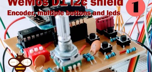
relay need a lot of power to be switched, I describe a little PCB here
WeMos D1 (esp8266) manage relay and shield
as you can see in the article, the solution is to use a transistor.
Bye Renzo
Thank you for the quick reply!
The IC (ULN2003) that I use is an array of darlington transistors couple that should deliver the power required.
Hi jordan,
open a topic in the forum and add your code, and we are going to check it.
Bye Renzo
Hello Renzo, love your post.
I’m doing now a engineer project for my degree and i have a problem. Im using a freenove esp32-wrover-cam(i can post a link to a pinout of this esp32).
https://makeradvisor.com/wp-content/uploads/2023/02/Freenove-ESP32-Wrover-CAM-pinout.jpg
I’m using a cam and wifi on this board, and also i need 7 pins to run other elements (3 buttons, 2 i2c(SDA SLC) for a 64×128 oled display, 1 pin to control POWER LED converter and 1 pin to control transistor controling a small motor). Because of my need of usage a cam and wifi i only left with two ports, 32 and 33, because CAM is disabling all cam ports and wifi is disabling all ACD2 ports. And one of sollutions i found is i2c expander like PCF8574, I managed to emulate i2c on 32 and 33 ports to turn on an display so i thought it would work with expander that way. I bought PCV8574 and i connected it with esp32
esp32 -> pcf8574
vcc -> vcc
GND->GND
32 -> SCL
33-> SDA
I tried to programm a simple code to test a button state read, but it doesn’t work
#include
#include "PCF8574.h"

// Instantiate Wire for generic use at 400kHz
TwoWire I2Cone = TwoWire(0);
// Instantiate Wire for generic use at 100kHz
TwoWire I2Ctwo = TwoWire(1);

// Set i2c address
PCF8574 pcf8574(&I2Ctwo, 0x20);
 //PCF8574 pcf8574(&I2Ctwo, 0x20, 32, 33);
// PCF8574(TwoWire *pWire, uint8_t address, uint8_t interruptPin,  void (*interruptFunction)() );
// PCF8574(TwoWire *pWire, uint8_t address, uint8_t sda, uint8_t scl, uint8_t interruptPin,  void (*interruptFunction)());

//#define I2C_SDA 33
//#define I2C_SCL 32
//Wire.begin(I2C_SDA, I2C_SCL);

void setup() {
    Serial.begin(115200);
  // put your setup code here, to run once:
I2Cone.begin(33,32,400000); // SDA pin 33, SCL pin 32, 400kHz frequency

pcf8574.pinMode(P2, INPUT_PULLUP);
pcf8574.begin();
}

void loop() {
  // put your main code here, to run repeatedly:
int buttonState = pcf8574.digitalRead(P2);
Serial.println(buttonState);
}
I connecter the bottom with P2 port and it doesn’t work. I don’t know if my esp32 is connecting to this expander or not.
Also another important question, can I emulate a SDA and SCL ports for my display on PCF8574 ports(P0-P7), or i can use other SDA SCL ports on other side of the PCF8574 board? If not then only solluction i have is to use 2 esp32 for this project, or but a 16GPIO expander and use
Hi Eryk,
Try to launch an i2c scanner and check if the device find It.
In the same i2c you can connect multiple device like expander and old display (i di the same here with an esp8266)
LoRa remote water level and pump controller (esp8266): server software – 2
esp32 is more powerful and can do it better.
If you need some specified information use the forum, we can put coffee and immerge and can be more simple to manage.
Bye Renzo
if the pin is being driven LOW by an external signal, it will read as LOW.
Hi Renzo, congratulations on your work. I’m using your library on an ESP8266 (ESP01s). I was wondering if it was possible to use a pin of the PCF8574 as an input for the 1-Wire protocol and obviously read a DS18B20. I’ve done research and various tests but nothing concrete for now. Thank you very much for any response.
Hi Tommaso,
I don’t know if It’s possible, I think the speed can be sufficient, but you must try, but you must reimplement the protocol and can be tedious.
Bye Renzo
Hi Renzo, thanks so much for the reply. I was starting to imagine the difficulty of implementation. If I find a way, maybe, I’ll leave a message. Good work!
Good work to you, if I find something that can be useful I write to you.
Bye Renzo
Good day, Renzo, I have trouble finding out why my first led or P0 is turned ON or at LOW when it should be turned OFF or HIGH, for the schematics I just followed your example at “Esp32 LEDs blink using a secondary i2c channel.” here’s my code
#include #include #include #include “Arduino.h” #include “PCF8574.h” TwoWire I2Cone = TwoWire(0); TwoWire I2Ctwo = TwoWire(1); PCF8574 pcf8574( & I2Ctwo, 0x20); BLEServer * pServer; BLECharacteristic * pCharacteristic; int ledPin = -1; int newLedPin; void setup() { Serial.begin(112560); I2Cone.begin(21, 22, 400000); for (int i = 0; i createService(BLEUUID(“19 B10001 - E8F2 - 537E-4 F6C - D104768A1214”)); pCharacteristic = pService -> createCharacteristic( BLEUUID(“19 B10001 - E8F2 - 537E-4 F6C - D104768A1214”), BLECharacteristic::PROPERTY_READ | BLECharacteristic::PROPERTY_WRITE ); pCharacteristic -> setValue(“0”); pService -> start(); BLEAdvertising * pAdvertising = BLEDevice::getAdvertising(); pAdvertising -> addServiceUUID(pService -> getUUID()); pAdvertising -> start(); Serial.println(“Setup complete.”); } void loop() { std::string value = pCharacteristic -> getValue(); if (!value.empty()) { newLedPin = value[0]–‘ 0’; if (newLedPin >= 0 && newLedPin <= 7) { ledPin = newLedPin; } // Serial.print("Received value: "); // Serial.println(value.c_str()); } if (ledPin != -1) { for (int i = 0; i < 8; i++) { pcf8574.digitalWrite(i, (i == ledPin) ? LOW : HIGH); } } delay(10); }Hi cy,
follow the examples and the sketch in the articles, you must add the begin and the pinMode for every pins.
Bye Renzo
добрый день.
в последнем примере на этой странице нарисован arduino uno
будет ли эта схема работать с esp8266 ?
Hi Alex,
you can find an example for esp8266 here.
Bye Renzo
I made my code to work with:
PCF8574.digitalWrite(1, HIGH);
and not
PCF8574.digitalWrite(P1, HIGH);
(for reference this is my code, where I’m using the code)
—————————————————————————————-
//varables
int useextenders;
int incomingnumberdigit3;
int incomingnumberdigit2;
int incomingnumberdigit1;
void setup(){

}
void loop() {
if( incomingnumberdigit2 == 6 ) {
    useextenders = 0;
  } else  {
    useextenders = 1;
  }

  if (incomingnumberdigit1 == 1) {
    if (useextenders == 1) {
      if (incomingnumberdigit2 == 1){
        expander1.digitalWrite(incomingnumberdigit3,HIGH);
      }if (incomingnumberdigit2 == 2){
        expander2.digitalWrite(incomingnumberdigit3,HIGH);
      }if (incomingnumberdigit2 == 3){
        expander3.digitalWrite(incomingnumberdigit3,HIGH);
      }if (incomingnumberdigit2 == 4){
        expander4.digitalWrite(incomingnumberdigit3,HIGH);
      }if (incomingnumberdigit2 == 5){
        expander5.digitalWrite(incomingnumberdigit3,HIGH);
      }
    }else{
      digitalWrite(incomingnumberdigit3 + 1,HIGH);
  }
  } else {
     if (useextenders == 1) {
      if (incomingnumberdigit2 == 1){
        expander1.digitalWrite(incomingnumberdigit3,LOW);
      }if (incomingnumberdigit2 == 2){
        expander2.digitalWrite(incomingnumberdigit3,LOW);
      }if (incomingnumberdigit2 == 3){
        expander3.digitalWrite(incomingnumberdigit3,LOW);
      }if (incomingnumberdigit2 == 4){
        expander4.digitalWrite(incomingnumberdigit3,LOW);
      }if (incomingnumberdigit2 == 5){
        expander5.digitalWrite(incomingnumberdigit3,LOW);
      }
    }else{
      digitalWrite(incomingnumberdigit3 + 1, LOW);
    }
  }
——————————————————————————————————————————–
if someone is using the expanders, you would expect them to be using more then 5 pins right? why cant I use a int type var to write to the pins?
Hi Someone,
you can use int variable without a problem, and I suggest ti use an array of expanders instead use if programming.
Bye Renzo
Hi,
In section Constructor /ESP32 there is an error in code:
line 10:
//DHT12 dht12(&I2Ctwo,21,22,0x5C);
this is the good syntactic:
//DHT12 dht12(&I2Ctwo,0x5C,21,22);
(i know it commented, but it killed lot of hours…)
Thanks a lor Sandor.
Bye Renzo