
PCF8574 i2c digital I/O expander: Arduino, esp8266 and esp32, rotary encoder – Part 2
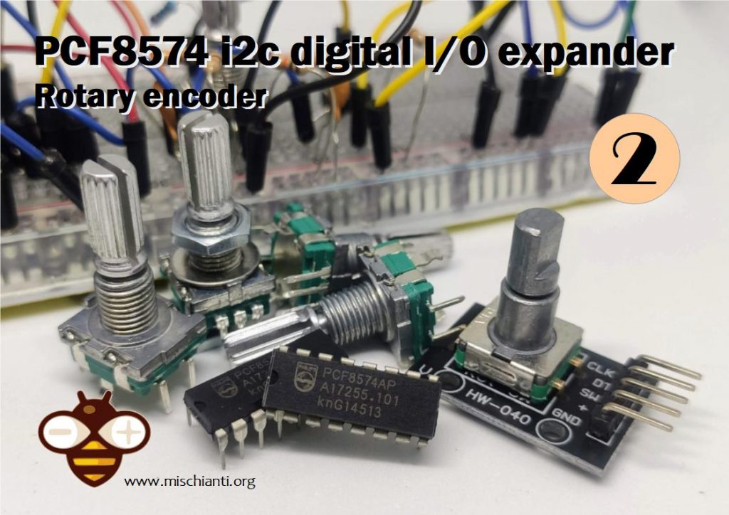
A rotary encoder, also called a shaft encoder, is an electro-mechanical device that converts the angular position or motion of a shaft or axle to analog or digital output signals.
Encoder introduction
Rotary encoders are used in a wide range of applications that require monitoring or control, or both, of mechanical systems, including industrial controls, robotics, photographic lenses, computer input devices such as optomechanical mice and trackballs, controlled stress rheometers, and rotating radar platforms.
You can buy as module or only the encoder
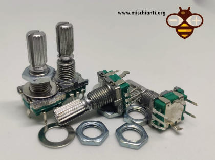
You can find rotary encoder on AliExpress
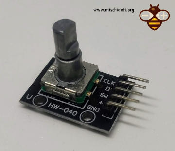
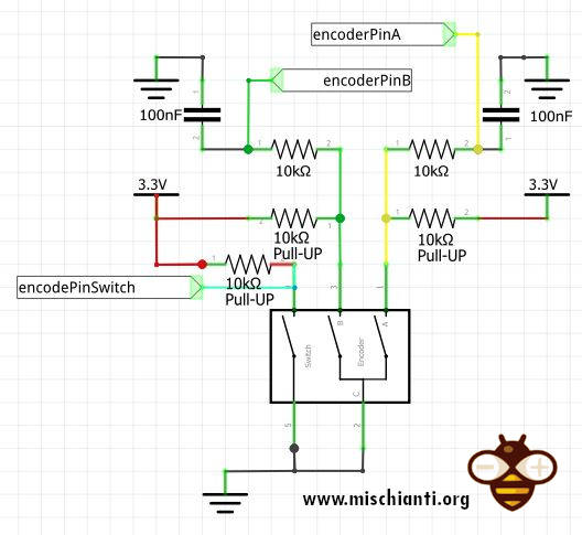
Module is more simple to manage, the most tedious problem of a rotary encoder is the noise generated. Module have only a simple pull-up resistor to reduce noise, but if you want use the encoder in native format you must apply a pull-up resistor and a simple filter.
For pull-UP I use a 10k resistor connected to the VCC, for the filter I use a 10k resistor from encoderPin and a 100nF capacitor connected to the GND.
The encoder work with the rotation of plate that connect switch.
The movement generate a predeterminated sequence:
So we must decode this sequence to get rotation versus and movement.
Library
You can find my library here.
To download.
Click the DOWNLOADS button in the top right corner, rename the uncompressed folder PCF8574.
Check that the PCF8574 folder contains PCF8574.cpp and PCF8574.h.
Place the PCF8574 library folder your /libraries/ folder.
You may need to create the libraries subfolder if its your first library.
Restart the IDE.
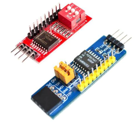
IC or Module
You can use a normal IC or module.
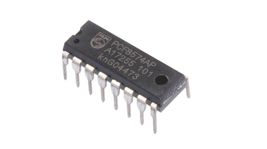
You can find pcf8574 on AliExpress
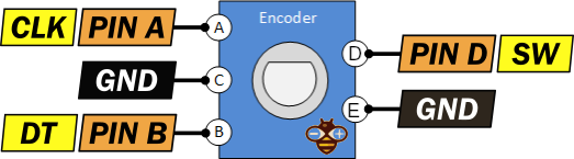
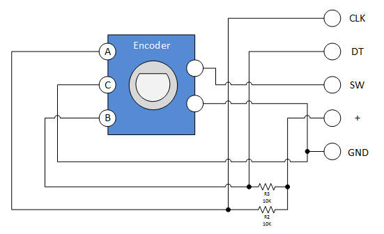
Connection schema
As we explain to connect an encoder to pcf8574 or directly to microcontroller you need a filter to reduce noise, or you must use a module.
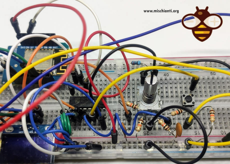
Here a complete connection schema on breadboard.
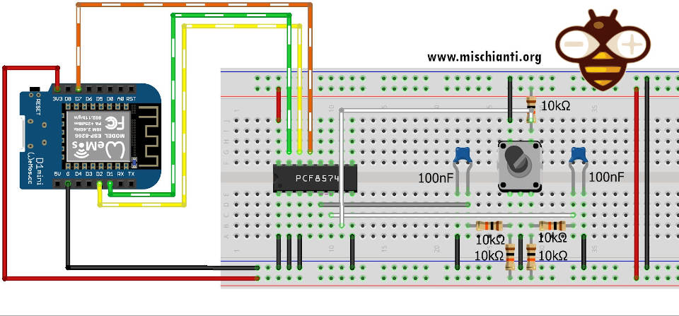
That result in this photo.
Examples sketch
pcf8574 and encoder: basic use
Here a basic sketch that use a basic features of my library.
/*
 * PCF8574 GPIO Port Expand
 * https://mischianti.org
 *
 * PCF8574    ----- WeMos
 * A0         ----- GRD
 * A1         ----- GRD
 * A2         ----- GRD
 * VSS        ----- GRD
 * VDD        ----- 5V/3.3V
 * SDA        ----- D1(PullUp)
 * SCL        ----- D2(PullUp)
 * INT        ----- INT(PullUp)
 *
 * P0     ----------------- ENCODER PIN A
 * P1     ----------------- ENCODER PIN B
 * P2     ----------------- ENCODER BUTTON
 *
 */
#include "Arduino.h"
#include "PCF8574.h"

int encoderPinA = P0;
int encoderPinB = P1;

#define INTERRUPTED_PIN D7

void ICACHE_RAM_ATTR updateEncoder();

// initialize library
PCF8574 pcf8574(0x38, INTERRUPTED_PIN, updateEncoder);

volatile long encoderValue = 0;
uint8_t encoderButtonVal = HIGH;

void setup()
{
	  Serial.begin (9600);
	  delay(500);

	  // encoder pins
	  pcf8574.pinMode(encoderPinA, INPUT_PULLUP);
	  pcf8574.pinMode(encoderPinB, INPUT_PULLUP);
	  // encoder button
	  pcf8574.pinMode(P2, INPUT_PULLUP);

	  // Set low latency with this method or uncomment LOW_LATENCY define in the library
	  // Needed for encoder
//	  pcf8574.setLatency(0);

	  // Start library
	  pcf8574.begin();
}

bool changed = false;

void loop()
{
	if (changed){
		Serial.print("ENCODER --> ");
		Serial.print(encoderValue);
		Serial.print(" - BUTTON --> ");
		Serial.println(encoderButtonVal?"HIGH":"LOW");
		changed = false;
	}
}

uint8_t encoderPinALast = LOW;
uint8_t valPrecEncoderButton = LOW;

void updateEncoder(){
	// Encoder management
	uint8_t n = pcf8574.digitalRead(encoderPinA, true);
	if ((encoderPinALast == LOW) && (n == HIGH)) {
		if (pcf8574.digitalRead(encoderPinB, true) == LOW) {
			encoderValue--;
			changed = true; // Chnged the value
		} else {
			encoderValue++;
			changed = true; // Chnged the value
		}
	}
	encoderPinALast = n;

	// Button management
	encoderButtonVal = pcf8574.digitalRead(P2);
	if (encoderButtonVal!=valPrecEncoderButton){
	  changed = true; // Chnged the value of button
	  valPrecEncoderButton = encoderButtonVal;
	}
}
There are some important thing to denote:
In the esp8266 to create a callback for the interrupt you must specify ICACHE_RAM_ATTR.
void ICACHE_RAM_ATTR updateEncoder();
Encoder pins is INPUT_PULLUP
	  // encoder pins
	  pcf8574.pinMode(encoderPinA, INPUT_PULLUP);
	  pcf8574.pinMode(encoderPinB, INPUT_PULLUP);
You must set low latency to the pcf8574 and there are 2 ways:
- use
pcf8574.setLatency(0);command that set to 0 the latency; - remove comment on
// #define PCF8574_LOW_LATENCY; - or better only for encoder use
pcf8574.digitalRead(encoderPinA, true)with additional parameter at true;
Now, we have a lot of false read and duplicate read (interrupt is generated for every veriation), even if we have set the filter.
So in the procedure we are going to check when the value is effective changed, and controlled by changed variable.
pcf8574 and econder optimized library features
Library get a set of method to do all operation in a trasparent mode.
Instead of use of pinMode you can use directly encoder like so.
PCF8574::encoder(uint8_t pinA, uint8_t pinB)
so the declaration become:
	// encoder pins
	pcf8574.encoder(encoderPinA, encoderPinB);
and all logic of encoder have 2 new manager, the first return the movement, like -1, 0 or 1.
int8_t PCF8574::readEncoderValue(uint8_t pinA, uint8_t pinB)
than the previous logic become
	int vale = pcf8574.readEncoderValue(encoderPinA, encoderPinB);
	if (vale!=0){
		changed = true;
	}
	encoderValue = encoderValue + vale;
another more pratival method is this:
bool PCF8574::readEncoderValue(uint8_t pinA, uint8_t pinB, volatile long *encoderValue)
that return if encoder have change is value (-1 or +1) and when you pass the reference of encoderValue the method update the external value.
So the code become:
changed = pcf8574.readEncoderValue(encoderPinA, encoderPinB, &encoderValue);
Here the previous sketch become
/*
 * PCF8574 GPIO Port Expand
 * https://mischianti.org
 *
 * PCF8574    ----- WeMos
 * A0         ----- GRD
 * A1         ----- GRD
 * A2         ----- GRD
 * VSS        ----- GRD
 * VDD        ----- 5V/3.3V
 * SDA        ----- D1(PullUp)
 * SCL        ----- D2(PullUp)
 * INT        ----- INT(PullUp)
 *
 * P0     ----------------- ENCODER PIN A
 * P1     ----------------- ENCODER PIN B
 * P2     ----------------- ENCODER BUTTON
 *
 */
#include "Arduino.h"
#include "PCF8574.h"

int encoderPinA = P0;
int encoderPinB = P1;

#define INTERRUPTED_PIN D7

void ICACHE_RAM_ATTR updateEncoder();

// initialize library
PCF8574 pcf8574(0x38, INTERRUPTED_PIN, updateEncoder);

volatile long encoderValue = 0;
uint8_t encoderButtonVal = HIGH;

void setup()
{
	Serial.begin (9600);
	delay(500);

	// encoder pins
	pcf8574.encoder(encoderPinA, encoderPinB);
	// encoder button
	pcf8574.pinMode(P2, INPUT_PULLUP);

	// Start library
	pcf8574.begin();

}

bool changed = false;

// The loop function is called in an endless loop
void loop()
{
	if (changed){
		Serial.print("ENCODER --> ");
		Serial.print(encoderValue);
		Serial.print(" - BUTTON --> ");
		Serial.println(encoderButtonVal?"HIGH":"LOW");
		changed = false;
	}
}

bool valPrec = LOW;
void updateEncoder(){
	changed = pcf8574.readEncoderValue(encoderPinA, encoderPinB, &encoderValue);

//	int vale = pcf8574.readEncoderValue(encoderPinA, encoderPinB);
//	if (vale!=0){
//		changed = true;
//	}
//	encoderValue = encoderValue + vale;

	bool val = pcf8574.digitalRead(P2);
	if (val!=valPrec){
	  changed = true;
	  valPrec = val;
	}
}
Demostration video
Thanks
- PCF8574 i2c digital I/O expander: Arduino, esp8266 and esp32, basic I/O and interrupt
- PCF8574 i2c digital I/O expander: Arduino, esp8266 and esp32, rotary encoder


The example you give calls bool val = pcf8574.digitalRead(P2); in the interrupt routine updateEncoder();.
Does that code bypass the Wire library as I’m sure I’ve read that Wire isn’t safe to use in an interrupt routine.
Hi Frank,
the interrupt is managed directly from the pcf8574 so It’s managed correctly though use i2c.
Bye Renzo
Hi Renzo,
I was wondering, if I connect 4 rotary encoders to a PCF8574(without connecting the encoder buttons), should I use pcf8574.encoder() 4 times, and then use the pcf8574.readEncoderValue() 4 times also, to return 4 different encoderValue?
Hi Mak,
I never test that situation, but I think It’s possible because I’m going to check the value of dedicated pins of the encoder and I compare the previous value.
remember you have only one interrupt so the change is in the same fucntion.
Bye Renzo
Thank You, Renzo!
Nice work!
Thanks to you for your support.
Hello, exactly what I was looking for, thanks!
However I can’t make it work for my ESP32S3, if I turn the knob there is a core dump following
“Guru Meditation Error: Core 1 panic’ed (Interrupt wdt timeout on CPU1). ”
If I don’t turn it, then nothing happens for a while, but then the core dump happens too.
It seems this has to do with the interrupt routine, and it is often warned that one should avoid putting in there complicated functions. Did you run this on an ESP32 too?
I Robert,
I don’t remember if I tested the specified case with ESP32s3, but I tested multiple times with ESP32 and ESP8266 without problem.
If I find some time, I will do some specified test.
Bye Renzo
Thanks!