bCNC Tutorial: autolevel – 2
One of the most important features of a CNC is the auto level. Even if your CNC is precise, it will never be accurate to one-hundredth of a millimeter, but to carry out the removal of copper, you will have to have a high precision level.
Auto level resolves the precision problem by creating a matrix of irregularity of your base. We are lucky also because copper is an excellent electrical conductor, so if you put a pole on the bit and one on the copper-clad, we can check all the surface.
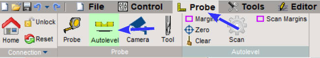
Now we must go to Probe Tab, select Auto level sub-tab, and have all the parameters to check to start work.
Remember to do the probe first of all.
First, you must check the speed of auto-level, these features can change for every CNC, but for my CNC that have 400 steps on Z, I use these values:
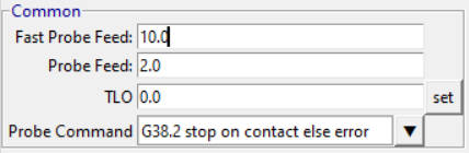
Fast Probe Feed is the probe’s initial speed, then when It’s pretty near the impact, enter in Probe Feed speed. In this case, we don’t have an additional probe tool, so the bit’s impact with copper is the 0 of the auto-level, so TLO (Tool offset) remains 0.
TLO is used when to probe you must use a particular device like a laminate, but you have a better idea in the image
If pole A is the bit and pole B is a conductive material, and you must probe the 0 to Wood’s surface, the TLO becomes 3mm (laminate height), and the software adds 3mm to the 0 contacts.
It is also useful to choose the area to probe for automatic leveling, my advice is to use the contour element (which is the largest area of your PCB) to define the edges of the leveling.
So we load a file of contour. File --> Open:
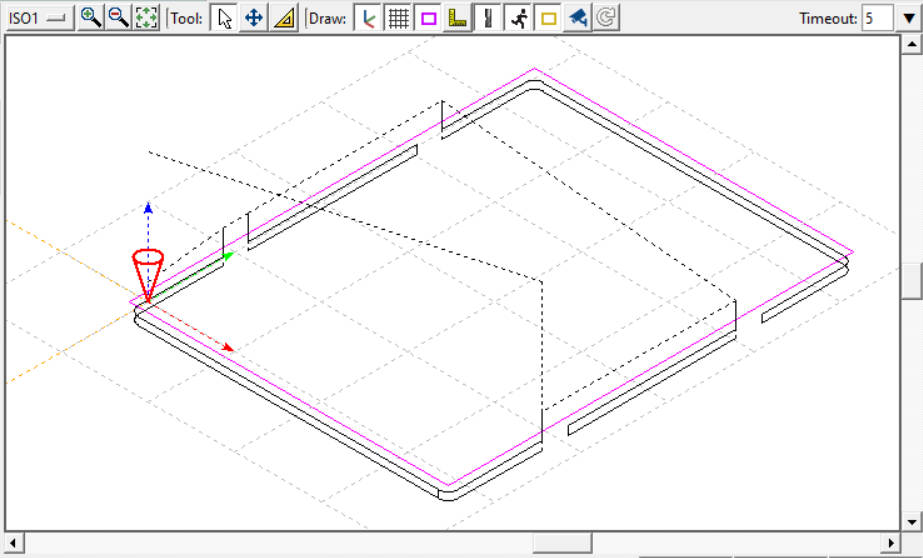
Now on the mini panel with all auto-level command
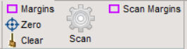
we select “Margins“, this button automatically generates margins for a complete auto-leveling matrix:
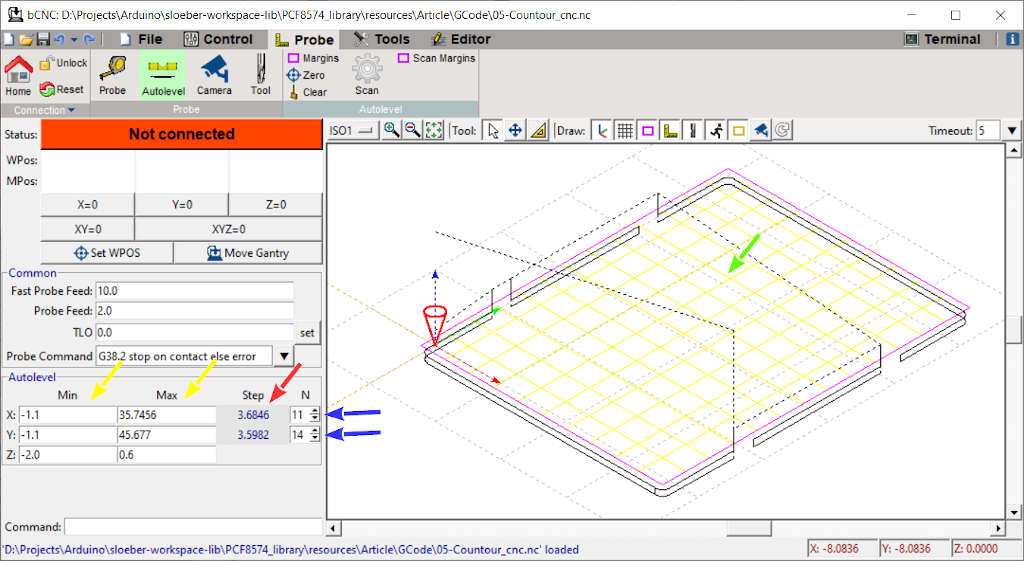
it set Min and Max (yellow arrows), Min is the minimum value to scan. To coordinate X and Y, you must set Z. I use the probe value -2.0mm, but a lesser value can be used. It’s the minimum value that It can reach from Z, typically 0.5mm it’s sufficient.
Max is the maximum value to scan, for coordinate X and Y, for Z, you must set a safe value to scan; 0.6 mm it’s sufficient.
Now you must select the size of the matrix; when you put the N value (red flag), you say to the machine the number of samples for X and Y, and when you put a more extensive value, the size of the matrix step is reduced to add more squares.
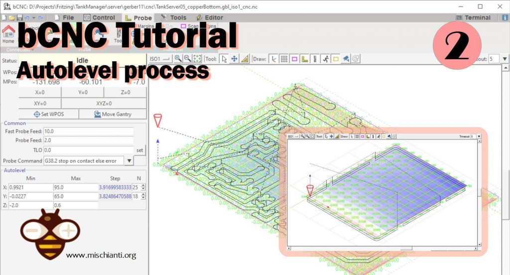
Then we click on the gear scan button to start.
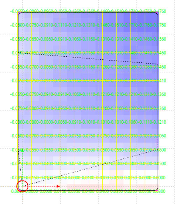
The result It’s a matrix with all the offset from the initial probe point
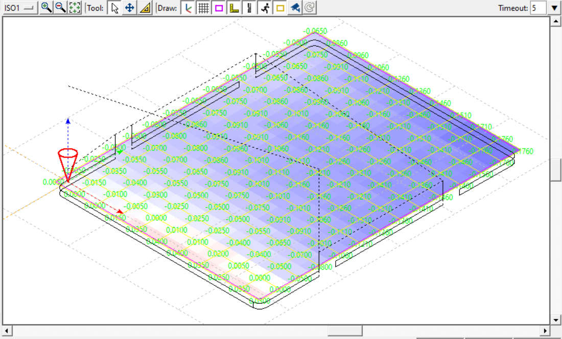
The red square means that It’s negative value respect to the 0 probe, white It’s the same value, and blue Its the upper value.
Save autolevel data
An important thing to do is save your autolevel data, which is essential above all, especially if you don’t do all operations simultaneously.
So when you finish auto-level, go to File --> Save and save a file with .probe extension. In the next chapter, we will see the steps to restart work when you power off the machine.
Thanks
- bCNC tutorial: installation, material and probe
- bCNC tutorial: autolevel
- bCNC tutorial: restart work and milling process