Connecting the EByte E70 to Arduino SAMD (Nano 33, MKR…) devices and a simple sketch example
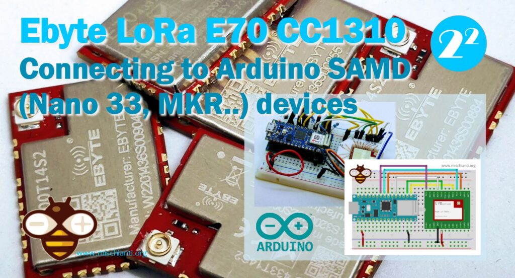
Welcome back to our series on connecting the EByte E70 to various devices! In this article, we’ll walk you through a simple sketch example that will help you establish a connection between the EByte E70 and your Arduino SAMD devices. So, let’s dive right in!
Understanding the EByte E70
The EByte E70 is a high-performance long-range transceiver module, renowned for its extensive communication range and low power consumption. Designed for wireless communication over large distances, it operates in the sub-GHz frequency bands, making it ideal for IoT applications that require reliable and efficient communication across wide areas.
Prerequisites
Before we begin, make sure you have the following:
- An Arduino Nano 33 IoT or MKR device
- The EByte E70 module with a breadboard adapter
- An Arduino IDE installed on your computer
- The necessary USB cables to connect your Arduino device and EByte E70 module to your computer
- Breadboard
Here the Arduino variants Arduino MKR WiFi 1010
Here the E70 variants E70 433/915 T S/S2 - E70 433/915 MT S
Setting up the Hardware
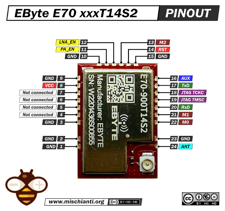
Pinout E70 xxxT14S2
I will use an E70 S2 version for my test because It’s a comfortable form factor with an onboard SMA antenna.
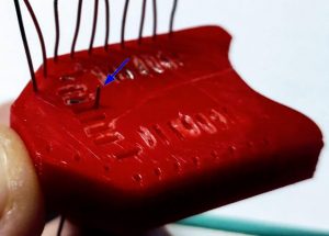
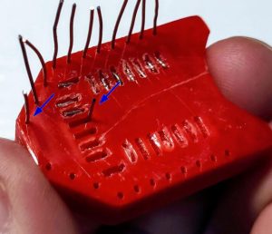
3D printed socket for breadboard
I created a simple socket with my 3D printer to quickly prototype (and manage) the E70 S2; here is the 3D model and the result on a breadboard.
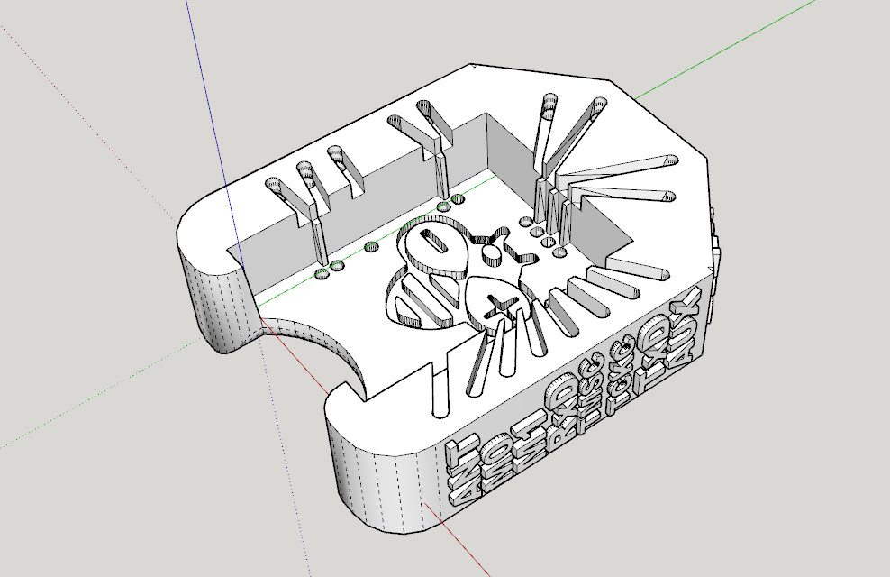
It’s very simple and uses the same technique as other sockets I already created.
After printing, you must add writing inside the hole.
Insert it into the innermost holes and push it out about 3mm
Bend the wire to the external of the adapter.
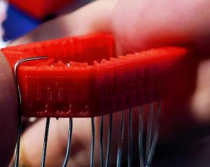
Cut the external part of the wire, and extract,
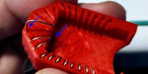
then reinsert in the internal and external holes.
Now check if you need to cut more of the wire of the internal hole and bend It.
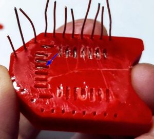
Repeat for all pins. The result It’s very satisfying.
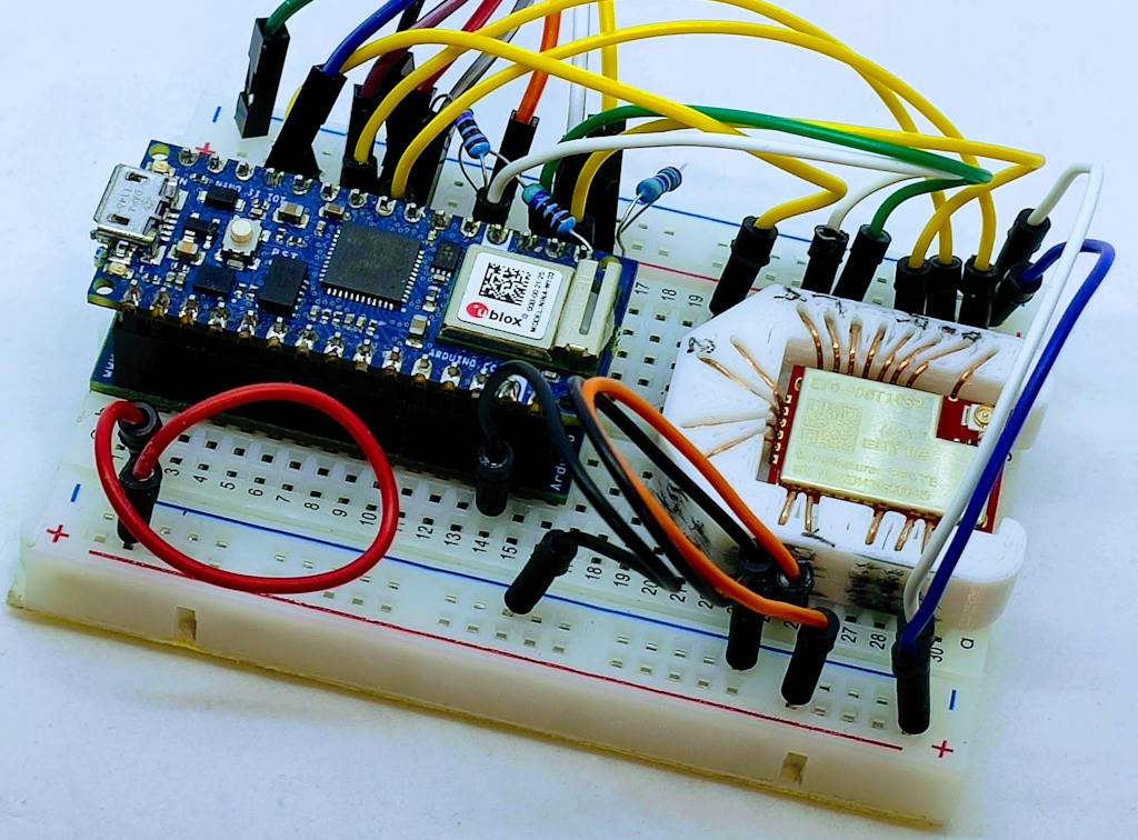
Wiring
Arduino Nano 33 IoT
The Arduino Nano 33 It’s a very versatile microcontroller with interesting capabilities.
Wiring.
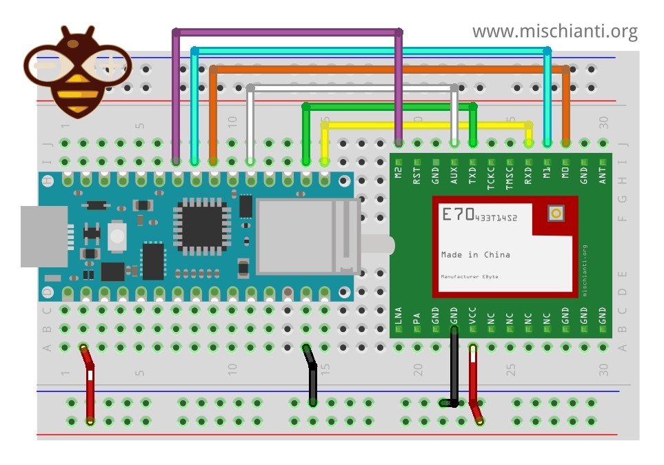
| E70 | Arduino Nano 33 IoT |
|---|---|
| M0 | 4 |
| M1 | 5 |
| M2 | 6 |
| TX | RX1 |
| RX | TX1 |
| AUX | 2 |
| VCC | 3.3v |
| GND | GND |
Constructor
RF_E70 e70ttl(&Serial1, 2, 4, 5, 6);
Arduino MKR WiFi
The Arduino MKR WiFi It’s the big brother of Nano 33.
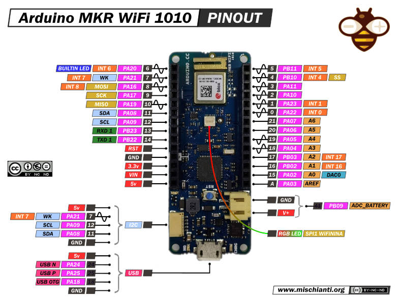
Wiring.
| E70 | Arduino Nano 33 IoT |
|---|---|
| M0 | 2 |
| M1 | 3 |
| M2 | 4 |
| TX | RX1 |
| RX | TX1 |
| AUX | 0 |
| VCC | 3.3v |
| GND | GND |
Constructor
RF_E70 e70ttl(&Serial1, 0, 2, 3, 4)
Configuring the Arduino IDE
I have written some articles about that, and you can find them here.
- Arduino SAMD NINA: pinout, specs and Arduino IDE configuration
- Arduino SAMD NINA: WiFiNINA, firmware update, and RGB led
- Arduino SAMD (NANO 33 and MKR): SPI flash memory FAT FS
- i2c Arduino SAMD MKR: additional interface SERCOM, network and address scanner
- Arduino MKR SAMD: FAT filesystem on external SPI flash memory
- Connecting the EByte E70 to Arduino SAMD (Nano 33, MKR…) devices and a simple sketch example
With the Arduino IDE configured, we can now proceed to the sketch example.
Library installation
You can find the library on GitHub.
But for simplicity, I added it to the Arduino Library manager.
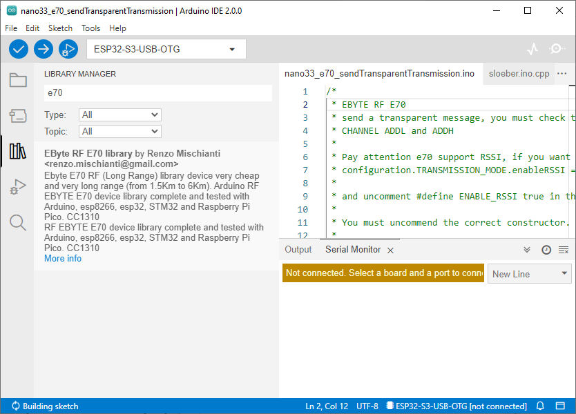
Writing the Sketch
The library offers a lot of examples, and you must only uncomment the correct constructor.
/*
 * EByte RF E70
 * send a transparent message, you must check that the transmitter and receiver have the same
 * CHANNEL ADDL and ADDH
 *
 * You must uncommend the correct constructor.
 *
 * by Renzo Mischianti <https://www.mischianti.org>
 *
 * https://www.mischianti.org
 *
 * E70		  ----- WeMos D1 mini	----- esp32			----- Arduino Nano 33 IoT	----- Arduino MKR	----- Raspberry Pi Pico   ----- stm32               ----- ArduinoUNO
 * M0         ----- D6 				----- 19 			----- 4 					----- 2 			----- 9 			      ----- PB0 		       	----- 8 Volt div
 * M1         ----- D7 				----- 21 			----- 5 					----- 3 			----- 10 			      ----- PB1 		       	----- 7 Volt div
 * M1         ----- D8 				----- 22 			----- 6 					----- 4 			----- 11 			      ----- PB10 		      	----- 6 Volt div
 * TX         ----- D3 (PullUP)		----- RX2 (PullUP)	----- RX1 (PullUP)			----- 14 (PullUP)	----- 8 (PullUP)	      ----- PA2 RX2 (PullUP)    ----- 4 (PullUP)
 * RX         ----- D4 (PullUP)		----- TX2 (PullUP)	----- TX1 (PullUP)			----- 13 (PullUP)	----- 9 (PullUP)	      ----- PA3 TX2 (PullUP)    ----- 5 Volt div (PullUP)
 * AUX        ----- D5 (PullUP)		----- 15  (PullUP)	----- 2  (PullUP)			----- 0  (PullUP)	----- 2  (PullUP)	      ----- PA0  (PullUP)       ----- 3 (PullUP)
 * VCC        ----- 3.3v/5v			----- 3.3v/5v		----- 3.3v/5v				----- 3.3v/5v		----- 3.3v/5v		      ----- 3.3v/5v             ----- 3.3v/5v
 * GND        ----- GND				----- GND			----- GND					----- GND			----- GND			      ----- GND                 ----- GND
 *
 *	Sub-packet can be emulated by set
 *	M0 = LOW
 *	M1 = HIGH
 *	M2 = LOW
 *	Continuous
 *	M0 = HIGH
 *	M1 = LOW
 *	M2 = LOW
 *
 */

#include "Arduino.h"
#include "RF_E70.h"

// ---------- esp8266 pins --------------
//RF_E70 e70ttl(RX, TX, AUX, M0, M1, M2);  // Arduino RX <-- e70 TX, Arduino TX --> e70 RX
//RF_E70 e70ttl(D3, D4, D5, D7, D6, D7); // Arduino RX <-- e70 TX, Arduino TX --> e70 RX AUX M0 M1
//RF_E70 e70ttl(D2, D3); // Config without connect AUX and M0 M1

//#include <SoftwareSerial.h>
//SoftwareSerial mySerial(D2, D3); // Arduino RX <-- e70 TX, Arduino TX --> e70 RX
//RF_E70 e70ttl(&mySerial, D5, D6, D7, D8); // AUX M0 M1
// -------------------------------------

// ---------- Arduino pins --------------
//RF_E70 e70ttl(4, 5, 3, 8, 7, 6); // Arduino RX <-- e70 TX, Arduino TX --> e70 RX AUX M0 M1
//RFF_E70 e70ttl(4, 5); // Config without connect AUX and M0 M1

//#include <SoftwareSerial.h>
//SoftwareSerial mySerial(4, 5); // Arduino RX <-- e70 TX, Arduino TX --> e70 RX
//RF_E70 e70ttl(&mySerial, 3, 8, 7, 6); // AUX M0 M1
// -------------------------------------

// ------------- Arduino Nano 33 IoT -------------
RF_E70 e70ttl(&Serial1, 2, 4, 5, 6); //  RX AUX M0 M1
// -------------------------------------------------

// ------------- Arduino MKR WiFi 1010 -------------
// RF_E70 e70ttl(&Serial1, 0, 2, 3, 4); //  RX AUX M0 M1
// -------------------------------------------------

// ---------- esp32c3 pins --------------
// RF_E70 e70ttl(&Serial1,  1, 2, 3, 4,); //  RX AUX M0 M1

//RF_E70 e70ttl(4, 5, &Serial1, 6, 1, 2, 3, UART_BPS_RATE_9600); //  esp32 RX <-- e70 TX, esp32 TX --> e70 RX AUX M0 M1
// -------------------------------------

// ---------- esp32 pins --------------
// RF_E70 e70ttl(&Serial2, 15, 19, 21, 22); //  RX AUX M0 M1

//RF_E70 e70ttl(&Serial2, 22, 4, 18, 21, 19, UART_BPS_RATE_9600); //  esp32 RX <-- e70 TX, esp32 TX --> e70 RX AUX M0 M1
// -------------------------------------

// ---------- Raspberry PI Pico pins --------------
// RF_E70 e70ttl(&Serial2, 2, 10, 11, 12); //  RX AUX M0 M1
// -------------------------------------

// ---------------- STM32 --------------------
// HardwareSerial Serial2(USART2);   // PA3  (RX)  PA2  (TX)
// RF_E70 e70ttl(&Serial2, PA0, PB0, PB1, PB10); //  RX AUX M0 M1
// -------------------------------------------------

 void setup() {
  Serial.begin(9600);
#if defined(ARDUINO_ARCH_STM32) || defined(__STM32F1__) || defined(__STM32F4__)
	Serial.dtr(false);
#endif

  delay(500);

  // Startup all pins and UART
  e70ttl.begin();

//  e70ttl.setMode(MODE_CONTINUOUS_1);

//  If you have ever change configuration you must restore It

  Serial.println("Hi, I'm going to send message!");
  // Send message
  ResponseStatus rs = e70ttl.sendMessage("Hello, world?");
  // Check If there is some problem of succesfully send
  Serial.println(rs.getResponseDescription());
}

void loop() {
	// If something available
  if (e70ttl.available()>1) {
	  // read the String message
	ResponseContainer rc = e70ttl.receiveMessage();
	// Is something goes wrong print error
	if (rc.status.code!=1){
		Serial.println(rc.status.getResponseDescription());
	}else{
		// Print the data received
		Serial.println(rc.status.getResponseDescription());
		Serial.println(rc.data);
	}
  }
  if (Serial.available()) {
	  String input = Serial.readString();
	  e70ttl.sendMessage(input);
  }
}
Uploading the Sketch
Before uploading the sketch to your device, make sure you have selected the correct board and port in the Arduino IDE. Then, click on the “Upload” button to compile and upload the sketch.
Once the upload is complete, open the Serial Monitor by going to “Tools” > “Serial Monitor” or by pressing “Ctrl+Shift+M”. Set the baud rate to 9600, and you should see the received data from the EByte E70 module being displayed in the Serial Monitor.
Thanks
Congratulations! You have successfully connected the EByte E70 to your Arduino device with a simple sketch example.
- EByte RF E70 433/868/900 T14S2: pinout, datasheet and specs (1.5Km)
- EByte RF E70 Module Adapter: PCB, 3D Printed, Breadboard-Friendly Solution and configuration
- Connecting the EByte E70 to ESP32 c3/s3 devices and a simple sketch example
- Connecting the EByte E70 to Arduino SAMD (Nano 33, MKR…) devices and a simple sketch example
- Connecting the EByte E70 to STM32 (black/blue pill) devices and a simple sketch example
- Connecting the EByte E70 to Raspberry Pi Pico (rp2040) devices and a simple sketch example
- Exploring the Capabilities of the EByte RF E70 Module (esp32, STM32, Arduino, Raspberry Pi Pico)
- EByte RF E70 CC1310: exploring library (esp32, esp8266, STM32, Arduino, Raspberry Pi Pico)
- Configuration of EByte RF E70 Module (esp32, STM32, Arduino, Raspberry Pi Pico)