Dallas ds18b20 with Raspberry Pi Pico (rp2040): all OneWire topologies, long stubs and more devices
The DS18B20 is a digital temperature sensor that communicates using the OneWire protocol, and the Raspberry Pi Pico is a microcontroller board based on the RP2040 chip. In this article, we will explore how to connect DS18B20 sensors to a Raspberry Pi Pico using the OneWire protocol.
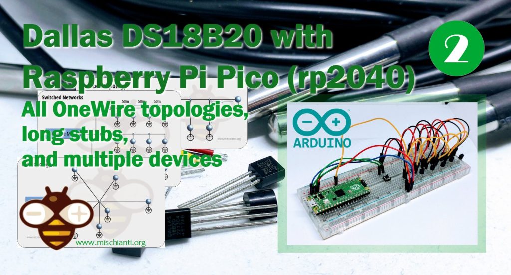
We will cover all possible OneWire topologies, including star, bus, and daisy chain, as well as methods for dealing with long stubs (long wires) that can cause signal degradation. Additionally, we will cover how to connect multiple DS18B20 sensors to the Raspberry Pi Pico, which can be useful in applications such as environmental monitoring or industrial automation.
Overall, the goal of this article is to provide a comprehensive guide for using DS18B20 sensors with a Raspberry Pi Pico, including troubleshooting tips and recommendations for optimizing sensor performance.
Features
- Unique 1-Wire® Interface Requires Only One Port Pin for Communication
- Reduce Component Count with Integrated Temperature Sensor and EEPROM
- Measures Temperatures from -55°C to +125°C (-67°F to +257°F)
- ±0.5°C Accuracy from -10°C to +85°C
- Programmable Resolution from 9 Bits to 12 Bits
- No External Components Required
- Parasitic Power Mode Requires Only 2 Pins for Operation (DQ and GND)
- Simplifies Distributed Temperature-Sensing Applications with Multidrop Capability
- Each Device Has a Unique 64-Bit Serial Code Stored in On-Board ROM
- Flexible User-Definable Nonvolatile (NV) Alarm Settings with Alarm Search Command Identifies Devices with Temperatures Outside Programmed Limits
- Available in 8-Pin SO (150 mils), 8-Pin µSOP, and 3-Pin TO-92 Packages
Datasheet
Pinout
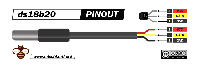
The sensor has more variants, but the wiring remains the same.
GND: connect to GND.
DATA: One-Wire Data bus.
VCC: power supply (3,3 – 5 V), but in parasite mode, you can connect to GND.
Here the sensor AliExpress
OneWire Network: Introduction
When you create a network, you must pay attention to the current-sense amplifiers (CSAs), which are used to measure the current flowing through a circuit. CSAs have benefits in various applications, including power management, motor control, and battery monitoring. There are different types of CSAs, including high-side and low-side amplifiers, and the various architectures used in their design.
We aren’t going into dept into the key specifications and performance parameters of CSAs, such as input offset voltage, bandwidth, and common-mode rejection ratio (CMRR). But we are going to describe different types of current-sensing resistors and how to select the right one for a particular application.
We move on to discuss practical considerations for using CSAs, including layout and grounding techniques, noise reduction, and temperature compensation. We show different application circuits for CSAs, such as simple voltage-to-current conversion, differential voltage sensing, and shunt-based current sensing.
OneWire network performance factors
The two critical measurements in 1-Wire network performance: are radius and weight. The radius of a 1-Wire network is the wire distance between the master and the farthest slave and is measured in meters. The weight of a 1-Wire network is the total length of wire in the network, also measured in meters.
For example, a 1-Wire network with a star configuration that has three branches of 10m, 20m, and 30m would have a radius of 30m (the distance from the master to the furthest slave) and a weight of 60m (the total length of wire in the network, which is 10m + 20m + 30m).
In general, the weight of the network limits the rise time on the cable, while the radius determines the timing of the slowest signal reflections. This information is essential for designing and troubleshooting 1-Wire networks to ensure that they operate efficiently and reliably.
OneWire Network Topologies
Although OneWire networks are often reasonably “free form” in structure, they usually fit into a few generalized categories based on the distribution of the 1-Wire slaves and the organization of the interconnecting wires.
Linear topology
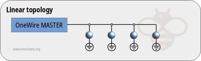
The 1-Wire bus is a single pair, starting from the master and extending to the farthest slave device. Other slaves are attached to the 1-Wire bus with insignificant (< 3m) branches or “stubs.”
Stubbed topology
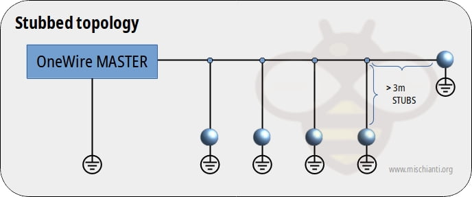
The 1-Wire bus is a single main line, starting at the master and extending to the farthest slave. Other slaves are attached to the main line through branches or stubs 3m or more in length.
Star topology
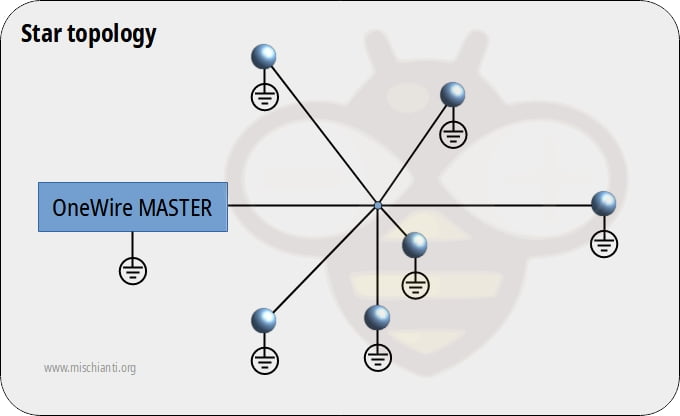
The 1-Wire bus is split at or near the master end and extends in multiple branches of varying lengths. There are slave devices along or at the ends of the branches.
Testing has shown that unswitched star-type network topologies (i.e., those with several branches diverging at the master) are the most difficult to make reliable. The junction of various branches presents highly mismatched impedances; reflections from the end of one branch can travel distances equal to nearly the weight of the network (rather than the radius) and cause data errors. For this reason, the unswitched star topology is not recommended, and no guarantees can be made about its performance.
When different topologies are intermixed, it becomes much more challenging to determine the practical limitations of the network. As a rule, the designer should apply the most conservative of the criteria in these cases.
Switched Networks
To allow networks to grow in complexity without growing in weight and radius, the network is divided into sections that are electronically switched on one at a time.
Using low-impedance, single-supply analog switches, the network can physically resemble one topology but electrically resemble another. This means that a star configuration with a switch on each branch would actually resemble a linear topology.
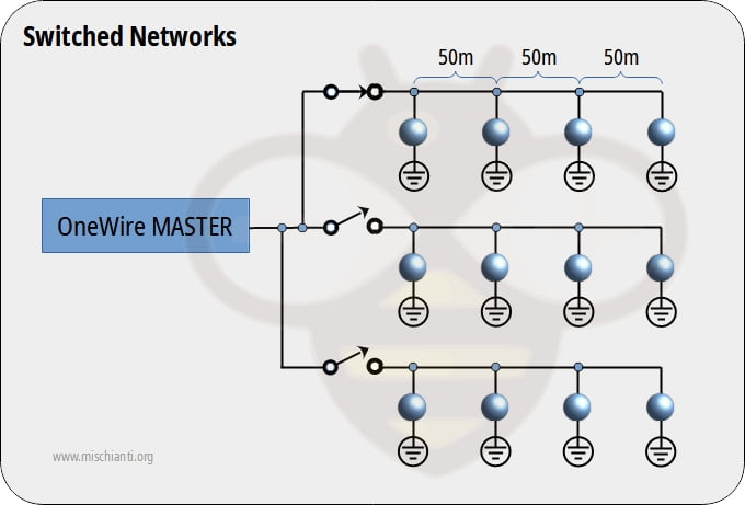
In this case, only one branch is active at any time. The example above appears like a star topology network with a radius of 150m and a weight of 450m. However, when each switched path is considered individually, the network is actually a linear topology, and the weight is only 150m. As a rule, our discussion of non-switched networks can be applied to each segment of a switched network.
OneWire network limitations
The maximum radius and weight of a OneWire network which is determined by several factors. Some of these factors can be controlled, while others cannot. The master-end interface plays a crucial role in determining the allowable size of a OneWire network. It must provide sufficient drive current to overcome the weight of the cable and slaves, generate OneWire waveforms with timings that are within specification and optimized for the charge and discharge times of the network, and provide a suitable impedance match to the network.
The radius of a 1-Wire network is limited by several factors, including the timing of waveform reflections, the time delay produced by the cable, the resistance of the cable, and the degradation of signal levels. The weight of the network is limited by the cable’s ability to be charged and discharged quickly enough to satisfy the 1-Wire protocol.
A simple resistor pullup has a weight limitation of about 200m. In comparison, the weight limit can be extended to over 500m by using sophisticated 1-Wire master designs with active pull-ups that provide higher currents under logic control.
The radius is limited by factors such as timing and cable resistance, while the weight is limited by the cable’s ability to be charged and discharged quickly enough. Active pull-ups can extend the weight limit of a 1-Wire network beyond the limitations of simple resistor pullups.
Parasite mode issues
The 1-Wire communication protocol not only facilitates communication but also provides operating power for the slaves. The slaves draw power from the bus when the voltage on the bus is greater than the voltage on their internal energy storage capacitor.
However, in networks with too many slaves, the current delivered by the master may not be sufficient to maintain operating voltage in the slaves, causing intermittent failures that are data-dependent.
The worst-case scenario for parasite power is a long sequence of zero bits issued by the master, as the bus spends most of its time in the low state, and there is little opportunity to recharge the slaves.
As the voltage in each slave drops, the slave’s ability to drive the bus decreases, eventually leading to a reset state where the slave stops responding.
When the slave receives sufficient operating voltage again, it will issue a presence pulse, which can corrupt other bus activity.
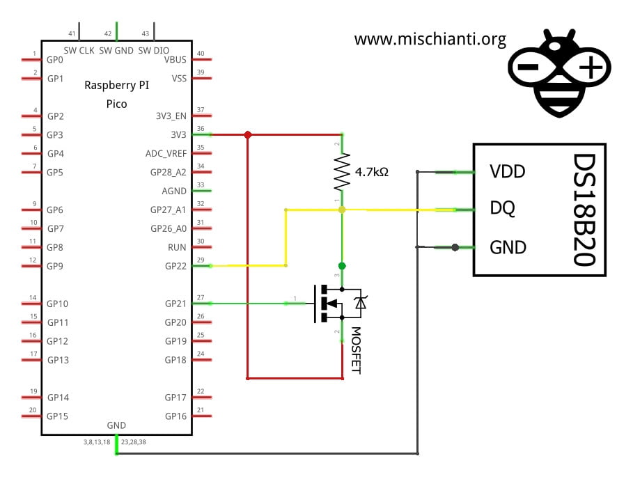
A possible solution is shown in the image above. In particular, it is used for ds18b20 temperature sensors.
The 1-Wire bus must be switched to the strong pullup within 10µs (max) after temperature conversions, and the bus must be held high by the pullup for the duration of the conversion or data transfer. No other activity can take place on the 1-Wire bus while the pullup is enabled.
The DS18B20 can also be powered by the conventional method of connecting an external power supply to the VDD pin, as shown. The advantage of this method is that the MOSFET pull-up is not required, and the 1-Wire bus is free to carry other traffic during the temperature conversion time.
Distribute impedance matching
The OneWire bus design is simple and low-cost, and additional components have typically been avoided.
However, when a stub is connected to the bus, there is an impedance mismatch at the branch point, which can cause reflections that interfere with other slaves on the network.
To mitigate this issue, a resistor in series with the stub can reduce the severity of the mismatch and the amplitude of the reflected energy.
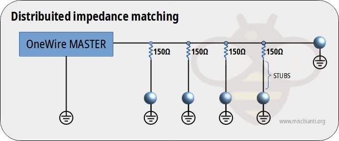
The most successful implementation of this concept uses 150½ resistors at each point where a stub is connected to the main trunk (consider 5v logic level). This reduces the mismatch at the connection point by about 20% and attenuates the resulting reflections by about 40%. However, caution is necessary as the added resistance can degrade noise immunity by about 80%.
Alternatively, 100½ resistor values have shown good performance and do not degrade noise immunity as much.
Pull-up resistor choice to fix troubleshooting
After some search in the network, I found some interesting solutions to improve the distance in a network with 3.3v logic.
In a medium distance network with DS18B20, worked on short cable, failed on 5M CAT3 cable. to resolve the problem, someone added an 80-ohm (a semi-randomly picked low value) resistor in series with the data line at both ends of the cable, which lowered the slew rate and fixed the problem for me.
With an unshielded CAT5 cable of about 40m and 7 sensors DS18B20. GROUND is connected to 2 wires from different twisted pairs. The last wires from these twisted pairs are used for DATA and power. Between GPIO4 and 3.3v, there is a 2.2k pullup resistor. The maker corrects data from the last 2 sensors on the wire, while one sensor in the middle always shows 85000. For me, it started to work when I changed the pullup resistor from 4,7k to 2.2k.
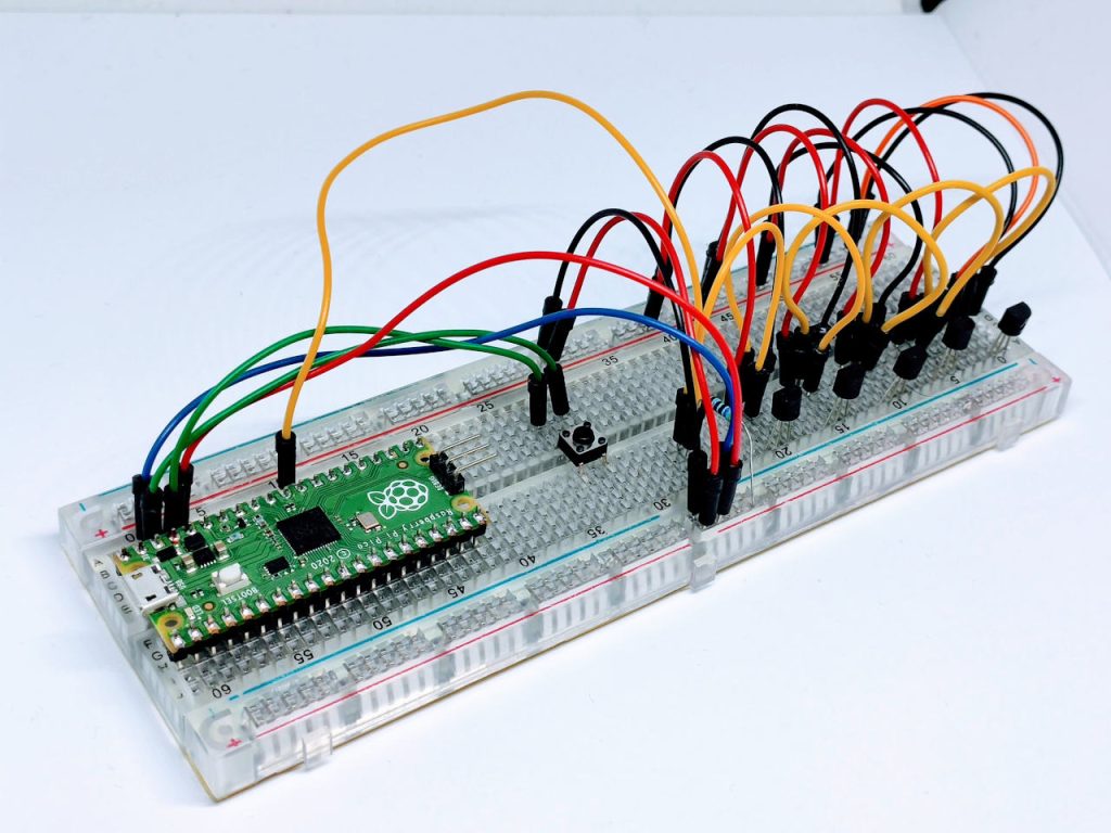
Wiring
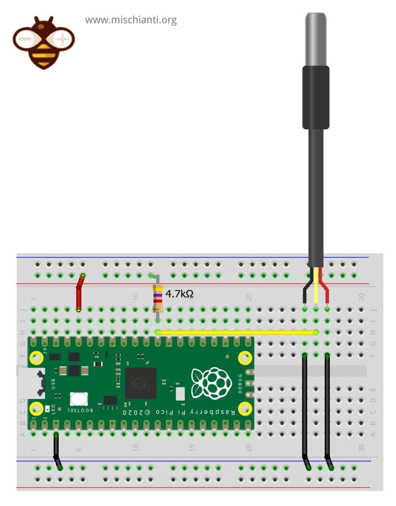
The One-Wire library Is a standard for all microcontrollers, so the device can be used with many microcontrollers. We already show the connection of the single sensor, now we are going to connect and manage multiple sensors.
If you need to connect only one sensor, refer to the previous article, “Dallas ds18b20 with Raspberry Pi Pico (rp2040): introduction and parasite mode”.
Raspberry Pi Pico normal mode
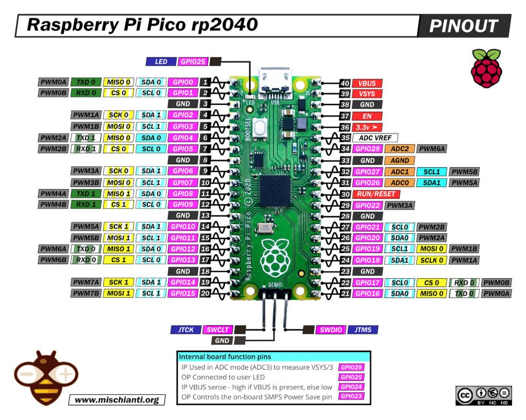
Here is the pinout of Raspberry Pi Pico prototype boards.
Or other variant:
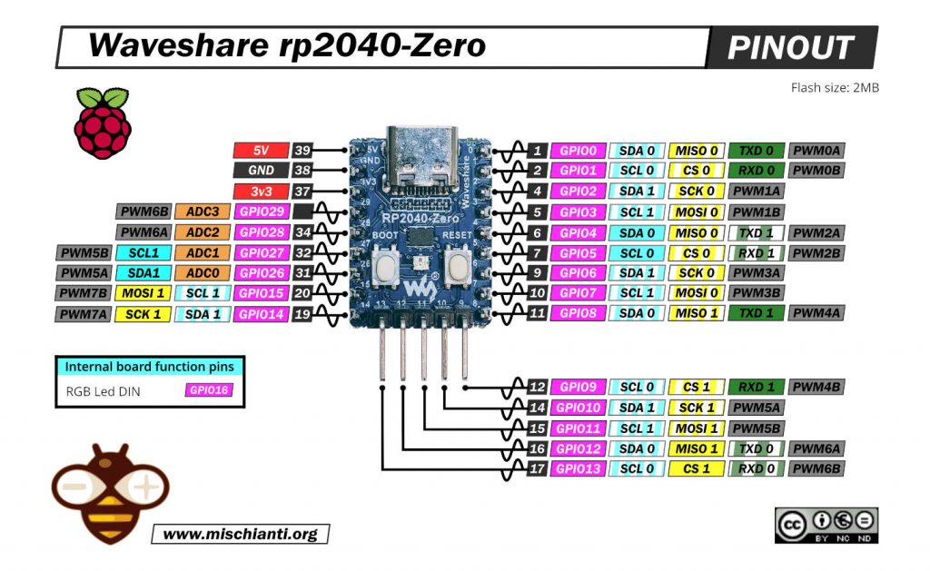
Here some rp2040 prototype board Official Pi Pico - Official Pi Pico W - Waveshare rp2040-zero - WeAct Studio rp2040
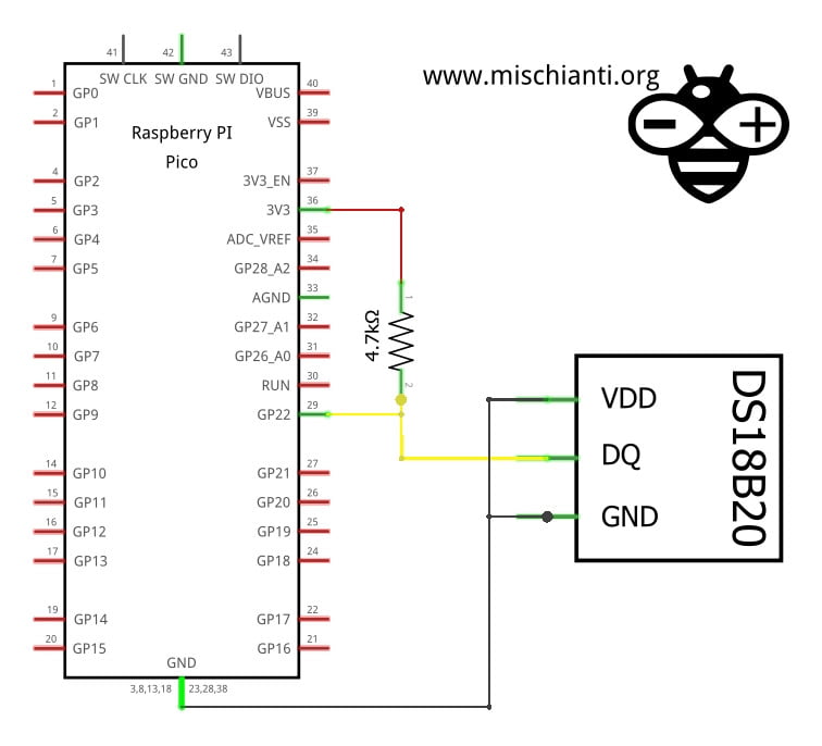
Normal mode
In normal mode, we are going to use a power line at 3.3v, so the connection becomes like so.
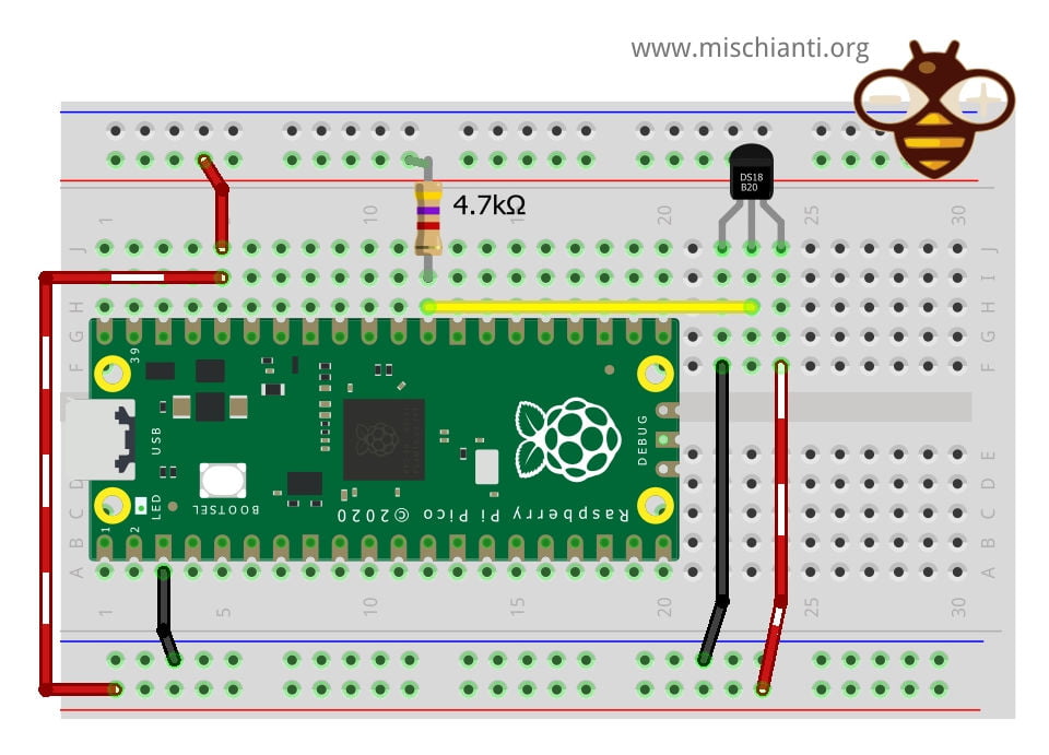
The connection is very simple.
| Raspberry Pi Pico | ds18b20 |
|---|---|
| GND | GND |
| 3.3v | VCC |
| D22 pulled-up | DATA |
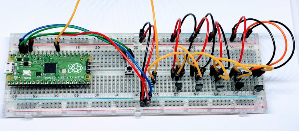
Normal mode multiple sensors in linear topology
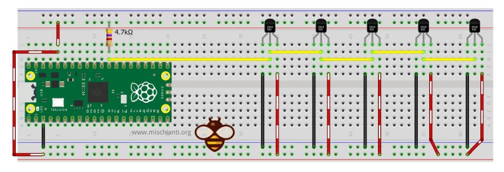
Parasite mode
In the parasite mode, you are going to put GND also in the VCC line of the sensor, and It gets the power from the Data line.
| Raspberry Pi Pico | ds18b20 |
|---|---|
| GND | GND |
| GND | VCC |
| D22 pulled-up | DATA |
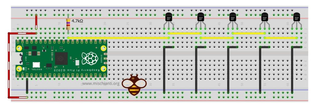
Parasite mode multiple sensors in linear topology
Library
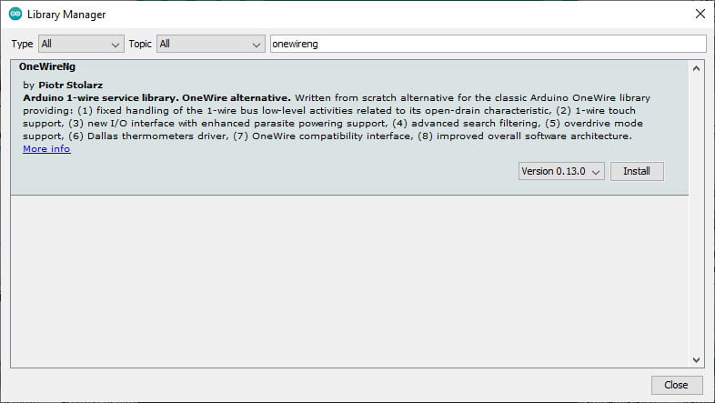
Now, when I write this article, there is a bug in the most famous library OneWire, so I insert the link to this library, so don’t use It.
Use OneWireNg not the standard OneWire library
Don’t use it until the bug is fixed.
First of all, you must remember that this sensor uses the One-Wire protocol, so you must add the OneWire library.
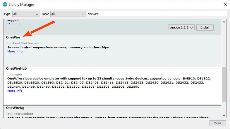
Use this for now
After that, you must install a library that implements the protocol and sensor features.
I chose the most widely used, the DallasTemperature (in the past Dallas, now Maxim).
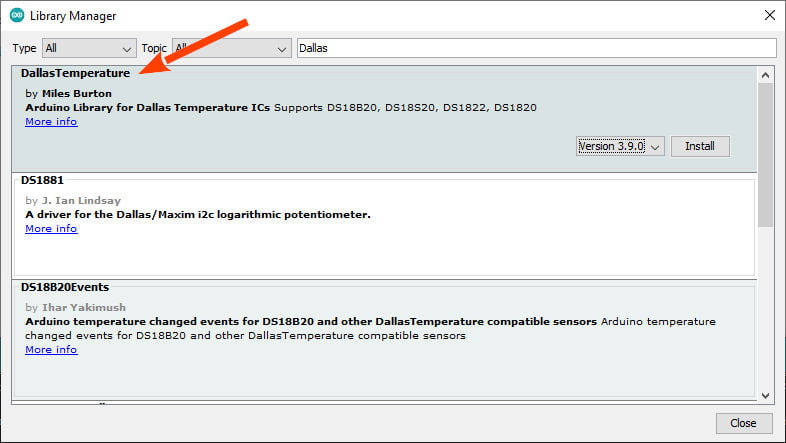
Devices supported
As described in the repository, this library supports the following devices :
- DS18B20
- DS18S20 (some problems on this device)
- DS1822
- DS1820
- MAX31820
- MAX31850
You will need a pull-up resistor of about 4.7KOhm between the 1-Wire data line and your VCC. if you are using the DS18B20, you can use parasite mode, and you can put to GND the VCC as described.
Troubleshooting
In case of temperature conversion problems (the result is -85), a strong pull-up setup may be necessary. See section Powering the DS18B20 in DS18B20 datasheet (page 7) and use DallasTemperature(OneWire*, uint8_t) constructor.
Powering the DS18B20 (normal/parasite)
The DS18B20 can be powered by an external supply on the VDD pin, or it can operate in “parasite power” mode, which allows the DS18B20 to function without a local external supply (you connect the VDD to the GND). DS18B20 “steals” power from the 1-Wire bus via the DQ pin when the bus is high. The stolen charge powers the DS18B20 while the bus is high, and some of the charges are stored on the parasite power capacitor (CPP) to provide power when the bus is low.
But when the DS18B20 performs temperature conversions or copies data from the scratchpad memory to EEPROM, the operating current can be as high as 1.5mA. This current can cause an unacceptable voltage drop across the weak 1-Wire pullup resistor and is more current than CPP can supply.
Strong pull-up for parasite mode
To assure that the DS18B20 has sufficient current supply, it is necessary to provide a strong pullup on the 1-Wire bus whenever temperature conversions occur or data is being copied from the scratchpad to EEPROM.
This can be accomplished by using a MOSFET to pull the bus directly to the rail.
The 1-Wire bus must be switched to the strong pullup within 10µs (max) after temperature conversions, and the bus must be held high by the pullup for the duration of the conversion or data transfer. No other activity can take place on the 1-Wire bus while the pullup is enabled.
The DS18B20 can also be powered by the conventional method of connecting an external power supply to the VDD pin, as shown. The advantage of this method is that the MOSFET pull-up is not required, and the 1-Wire bus is free to carry other traffic during the temperature conversion time.
The use of parasite power is not recommended for temperatures above +100°C since the DS18B20 may not be able to sustain communications due to the higher leakage currents that can exist at these temperatures.
Reduce the size of the library
We have included a REQUIRESNEW and REQUIRESALARMS definition. If you want to slim down the code, feel free to use either of these by including
#define REQUIRESNEW
or
#define REQUIRESALARMS
at the top of DallasTemperature.h
Code
When you operate with multiple devices, It’s essential to identify them univocally. We must remember that the ds18b20 has an internal address that can be used as uuid.
Search all sensors connected to the network
Here is a simple example that searches all OneWire devices connected to an interval of pins and generate a list of address that can be used to manage the ds18b20.
/**
 * OneWire Library example
 * Find all device (select starting end ending pin)
 *
 * Renzo Mischianti <www.mischianti.org>
 */

#define STARTING_PIN D22
#define ENDING_PIN D22

uint8_t findDevices(int pin);

#include <OneWire.h>

void setup()
{
  Serial.begin(115200);
  Serial.println("//\n// Start oneWire search \n//");

  for (uint8_t pin = STARTING_PIN; pin <= ENDING_PIN; pin++)
  {
    findDevices(pin);
  }
  Serial.println("\n//\n// End oneWire search \n//");
}

void loop()
{
}

uint8_t findDevices(int pin)
{
  OneWire ow(pin);

  uint8_t address[8];
  uint8_t count = 0;


  if (ow.search(address))
  {
    Serial.print("\nDeviceAddress pin");
    Serial.print(pin, DEC);
    Serial.println("[] = {");
    do {
      count++;
      Serial.print(" {");
      for (uint8_t i = 0; i < 8; i++)
      {
        Serial.print("0x");
        if (address[i] < 0x10) Serial.print("0");
        Serial.print(address[i], HEX);
        if (i < 7) Serial.print(", ");
      }
      Serial.println("  },");
    } while (ow.search(address));

    Serial.println("};");
    Serial.print("// nr devices found: ");
    Serial.println(count);
  }

  return count;
}
In my case, the Serial output is:
//
// Start oneWire search
//

DeviceAddress pin22[] = {
 {0x28, 0xFF, 0x64, 0x0E, 0x6C, 0x63, 0xD0, 0x15  },
 {0x28, 0xFF, 0x64, 0x0E, 0x6C, 0x6F, 0x7A, 0x89  },
 {0x28, 0xFF, 0x64, 0x0E, 0x6D, 0x64, 0x7F, 0x3E  },
 {0x28, 0xFF, 0x64, 0x0E, 0x6D, 0x5C, 0x1A, 0x3F  },
 {0x28, 0xFF, 0x64, 0x0E, 0x6D, 0x5D, 0x66, 0xA0  },
};
// nr devices found: 5

//
// End oneWire search
//
It correctly found 5 ds18b20 and generated the array of addresses.
Get info and temperature from an array of address
With the array of the previous sketch, we are going to do a sketch to read the temperature.
/**
 * From a list of thermostat address
 * generated with the previous search sketch
 * we are going to  get the
 * temperature of every device
 *
 * by Renzo Mischianti <www.mischianti.org>
 *
 * https://mischianti.org
 *
 */

// Include the libraries we need
#include <OneWire.h>
#include <DallasTemperature.h>

// Data wire is plugged into port D22
#define ONE_WIRE_BUS D22
#define TEMPERATURE_PRECISION 9

// Setup a oneWire instance to communicate with any OneWire devices (not just Maxim/Dallas temperature ICs)
OneWire oneWire(ONE_WIRE_BUS);

// Pass our oneWire reference to Dallas Temperature.
DallasTemperature sensors(&oneWire);

// The array generated from the search sketch
DeviceAddress pin22[] = {
 {0x28, 0xFF, 0x64, 0x0E, 0x6C, 0x63, 0xD0, 0x15  },
 {0x28, 0xFF, 0x64, 0x0E, 0x6C, 0x6F, 0x7A, 0x89  },
 {0x28, 0xFF, 0x64, 0x0E, 0x6D, 0x64, 0x7F, 0x3E  },
 {0x28, 0xFF, 0x64, 0x0E, 0x6D, 0x5C, 0x1A, 0x3F  },
 {0x28, 0xFF, 0x64, 0x0E, 0x6D, 0x5D, 0x66, 0xA0  },
};

void setup(void)
{
  // start serial port
  Serial.begin(115200);
  while (!Serial) {delay(100);}

  Serial.println("Dallas Temperature IC Control ");

  // Start up the library
  sensors.begin();

  // locate devices on the bus
  Serial.print("Locating devices...");
  Serial.print("Found ");
  Serial.print(sensors.getDeviceCount(), DEC);
  Serial.println(" devices.");

  // report parasite power requirements
  Serial.print("Parasite power is: ");
  if (sensors.isParasitePowerMode()) Serial.println("ON");
  else Serial.println("OFF");

  // set the temperature accurancy
  for (int i = 0; i < 5; i++) {
	  // set the resolution to 9 bit per device
	   sensors.setResolution(pin22[i], TEMPERATURE_PRECISION);
  }
}

// function to print a device address
void printAddress(DeviceAddress deviceAddress)
{
  for (uint8_t i = 0; i < 8; i++)
  {
    // zero pad the address if necessary
    if (deviceAddress[i] < 16) Serial.print("0");
    Serial.print(deviceAddress[i], HEX);
  }
}

// function to print the temperature for a device
void printTemperature(DeviceAddress deviceAddress)
{
  float tempC = sensors.getTempC(deviceAddress);
  if(tempC == DEVICE_DISCONNECTED_C)
  {
    Serial.println("Error: Could not read temperature data");
    return;
  }
  Serial.print("Temp C: ");
  Serial.print(tempC);
  Serial.print(" Temp F: ");
  Serial.print(DallasTemperature::toFahrenheit(tempC));
}

/*
   Main function, calls the temperatures in a loop.
*/
void loop(void)
{
  // call sensors.requestTemperatures() to issue a global temperature
  // request to all devices on the bus
  Serial.print("Requesting temperatures...");
  sensors.requestTemperatures();
  Serial.println("DONE");

  for (int i = 0; i < 5; i++) {
	  // print the device information
	  Serial.print("Device Address: ");
	  printAddress(pin22[i]);
	  Serial.print(" of ");
	  Serial.print(i);
	  Serial.print(" sensor -> ");
	  printTemperature(pin22[i]);
	  Serial.println();
  }

  delay(2000);
}
The result in the Serial output:
Dallas Temperature IC Control
Locating devices...Found 5 devices.
Parasite power is: OFF
Requesting temperatures...DONE
Device Address: 28FF640E6C63D015 of 0 sensor -> Temp C: 19.56 Temp F: 67.21
Device Address: 28FF640E6C6F7A89 of 1 sensor -> Temp C: 19.87 Temp F: 67.77
Device Address: 28FF640E6D647F3E of 2 sensor -> Temp C: 19.62 Temp F: 67.32
Device Address: 28FF640E6D5C1A3F of 3 sensor -> Temp C: 19.69 Temp F: 67.44
Device Address: 28FF640E6D5D66A0 of 4 sensor -> Temp C: 19.62 Temp F: 67.32
Requesting temperatures...DONE
Device Address: 28FF640E6C63D015 of 0 sensor -> Temp C: 19.62 Temp F: 67.32
Device Address: 28FF640E6C6F7A89 of 1 sensor -> Temp C: 19.81 Temp F: 67.66
Device Address: 28FF640E6D647F3E of 2 sensor -> Temp C: 19.62 Temp F: 67.32
Device Address: 28FF640E6D5C1A3F of 3 sensor -> Temp C: 19.69 Temp F: 67.44
Device Address: 28FF640E6D5D66A0 of 4 sensor -> Temp C: 19.62 Temp F: 67.32
Indexing the sensors and getting the temperature
A not very real solution is to index the sensors and get the temperature. This solution is not very useful because you can’t know which sensor becomes 0, 1.. and so on.
For simplicity, I reduce the sensors in line to 4.
/**
 * Indexing thermometer and read the temperature
 *
 * by Renzo Mischianti <www.mischianti.org>
 *
 * https://mischianti.org
 */
#include <OneWire.h>
#include <DallasTemperature.h>

// Data wire is plugged into port D22
#define ONE_WIRE_BUS D22
#define TEMPERATURE_PRECISION 9

// Setup a oneWire instance to communicate with any OneWire devices
OneWire oneWire(ONE_WIRE_BUS);

// Pass our oneWire reference to Dallas Temperature.
DallasTemperature sensors(&oneWire);

DeviceAddress firstThermometer, secondThermometer, thirdThermometer, fourthThermometer;

void setup(void)
{
  // start serial port
  Serial.begin(115200);
  Serial.println("Dallas Temperature IC Control Library Demo");

  // Start up the library
  sensors.begin();

  // locate devices on the bus
  Serial.print("Locating devices...");
  Serial.print("Found ");
  Serial.print(sensors.getDeviceCount(), DEC);
  Serial.println(" devices.");

  // report parasite power requirements
  Serial.print("Parasite power is: ");
  if (sensors.isParasitePowerMode()) Serial.println("ON");
  else Serial.println("OFF");

  // assigns the first address found to insideThermometer
  if (!oneWire.search(firstThermometer)) Serial.println("Unable to find 1 address for insideThermometer");
  // assigns the second address found to insideThermometer
  if (!oneWire.search(secondThermometer)) Serial.println("Unable to find 2 address for insideThermometer");
  // assigns the third address found to insideThermometer
  if (!oneWire.search(thirdThermometer)) Serial.println("Unable to find 3 address for insideThermometer");
  // assigns the fourth address found to insideThermometer
  if (!oneWire.search(fourthThermometer)) Serial.println("Unable to find 4 address for insideThermometer");

  // show the addresses we found on the bus
  Serial.print("Device 0 Address: ");
  printAddress(firstThermometer);
  Serial.println();

  Serial.print("Device 1 Address: ");
  printAddress(secondThermometer);
  Serial.println();

  Serial.print("Device 2 Address: ");
  printAddress(thirdThermometer);
  Serial.println();

  Serial.print("Device 3 Address: ");
  printAddress(fourthThermometer);
  Serial.println();

  // set the resolution to 9 bit per device
  sensors.setResolution(firstThermometer, TEMPERATURE_PRECISION);
  sensors.setResolution(secondThermometer, TEMPERATURE_PRECISION);
  sensors.setResolution(thirdThermometer, TEMPERATURE_PRECISION);
  sensors.setResolution(fourthThermometer, TEMPERATURE_PRECISION);

  Serial.print("Device 0 Resolution: ");
  Serial.print(sensors.getResolution(firstThermometer), DEC);
  Serial.println();

  Serial.print("Device 1 Resolution: ");
  Serial.print(sensors.getResolution(secondThermometer), DEC);
  Serial.println();

  Serial.print("Device 2 Resolution: ");
  Serial.print(sensors.getResolution(thirdThermometer), DEC);
  Serial.println();

  Serial.print("Device 3 Resolution: ");
  Serial.print(sensors.getResolution(fourthThermometer), DEC);
  Serial.println();
}

// function to print a device address
void printAddress(DeviceAddress deviceAddress)
{
  for (uint8_t i = 0; i < 8; i++)
  {
    // zero pad the address if necessary
    if (deviceAddress[i] < 16) Serial.print("0");
    Serial.print(deviceAddress[i], HEX);
  }
}

// function to print the temperature for a device
void printTemperature(DeviceAddress deviceAddress)
{
  float tempC = sensors.getTempC(deviceAddress);
  if(tempC == DEVICE_DISCONNECTED_C)
  {
    Serial.println("Error: Could not read temperature data");
    return;
  }
  Serial.print("Temp C: ");
  Serial.print(tempC);
  Serial.print(" Temp F: ");
  Serial.print(DallasTemperature::toFahrenheit(tempC));
}

// function to print a device's resolution
void printResolution(DeviceAddress deviceAddress)
{
  Serial.print("Resolution: ");
  Serial.print(sensors.getResolution(deviceAddress));
  Serial.println();
}

// main function to print information about a device
void printData(DeviceAddress deviceAddress)
{
  Serial.print("Device Address: ");
  printAddress(deviceAddress);
  Serial.print(" ");
  printTemperature(deviceAddress);
  Serial.println();
}

/*
   Main function, calls the temperatures in a loop.
*/
void loop(void)
{
  // call sensors.requestTemperatures() to issue a global temperature
  // request to all devices on the bus
  Serial.print("Requesting temperatures...");
  sensors.requestTemperatures();
  Serial.println("DONE");

  // print the device information
  printData(firstThermometer);
  printData(secondThermometer);
  printData(thirdThermometer);
  printData(fourthThermometer);

  delay(2000);
}
Every time you do a search, a new index is generated and assigned, and the search returns 1 when no other sensors are found It returns 0.
  // assigns the first address found to insideThermometer
  if (!oneWire.search(firstThermometer)) Serial.println("Unable to find 1 address for insideThermometer");
  // assigns the second address found to insideThermometer
  if (!oneWire.search(secondThermometer)) Serial.println("Unable to find 2 address for insideThermometer");
  // assigns the third address found to insideThermometer
  if (!oneWire.search(thirdThermometer)) Serial.println("Unable to find 3 address for insideThermometer");
  // assigns the fourth address found to insideThermometer
  if (!oneWire.search(fourthThermometer)) Serial.println("Unable to find 4 address for insideThermometer");
  // assigns the fifth address found to insideThermometer
  if (!oneWire.search(fifthThermometer)) Serial.println("Unable to find 5 address for insideThermometer");
  // assigns the sixth address found to insideThermometer
  if (!oneWire.search(sixthThermometer)) Serial.println("Unable to find 6 address for insideThermometer");
So the relevant and newest part of Serial output is highlighted.
Dallas Temperature IC Control Library Demo
Locating devices...Found 4 devices.
Parasite power is: OFF
Unable to find 5 address for thermometer
Device 0 Address: 28FF640E6C6F7A89
Device 1 Address: 28FF640E6D647F3E
Device 2 Address: 28FF640E6D5C1A3F
Device 3 Address: 28FF640E6D5D66A0
Device 0 Resolution: 12
Device 1 Resolution: 12
Device 2 Resolution: 12
Device 3 Resolution: 12
Requesting temperatures...DONE
Device Address: 28FF640E6C6F7A89 Temp C: 21.31 Temp F: 70.36
Device Address: 28FF640E6D647F3E Temp C: 21.19 Temp F: 70.14
Device Address: 28FF640E6D5C1A3F Temp C: 21.31 Temp F: 70.36
Device Address: 28FF640E6D5D66A0 Temp C: 21.19 Temp F: 70.14
Requesting temperatures...DONE
Device Address: 28FF640E6C6F7A89 Temp C: 21.31 Temp F: 70.36
Device Address: 28FF640E6D647F3E Temp C: 21.19 Temp F: 70.14
Device Address: 28FF640E6D5C1A3F Temp C: 21.25 Temp F: 70.25
Device Address: 28FF640E6D5D66A0 Temp C: 21.19 Temp F: 70.14
Thanks
- Raspberry Pi Pico and rp2040 boards: pinout, specs, and Arduino IDE configuration
- Raspberry Pi Pico and rp2040 boards: integrated LittleFS filesystem
- Raspberry Pi Pico and rp2040 board: ethernet w5500 with plain (HTTP) and SSL (HTTPS) requests
- Raspberry Pi Pico and rp2040 boards: WiFiNINA with ESP32 WiFi Co-Processor
- Raspberry Pi Pico and rp2040 boards: how to use SD card
- Dallas ds18b20
- Connecting the EByte E70 to Raspberry Pi Pico (rp2040) devices and a simple sketch example