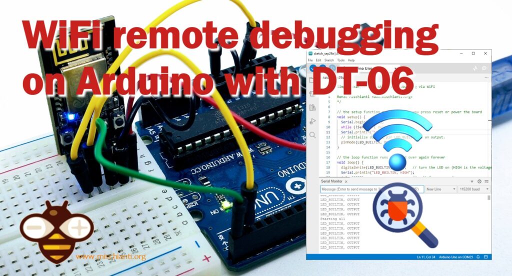
WiFi remote debugging of an Arduino with DT-06
We have already addressed the topic of remote wireless programming via Bluetooth of an Arduino UNO in our previous article titled “Arduino Remote/wireless Programming” however, thanks to the feedback and questions from our readers, we have decided to delve even deeper into this subject, exploring the possibilities that WiFi connectivity offers.
Many of you appreciated our article on the remote connection of an Arduino UNO inside the freezer :P, which provided a detailed guide on how to transmit a sketch to an Arduino using HC-05 Bluetooth modules. We are delighted to have assisted you in realizing your projects, but now we are taking on a new challenge: how can we extend the range of these wireless connections from just a few meters to a distance limited only by your WiFi coverage?
Throughout this article, we will explore the solutions available on the market and alternatives to HC-05 modules. We will discover how to achieve a more powerful and reliable wireless connection for your Arduino projects. So, if you’re ready to dive deeper into the world of remote programming via WiFi, keep reading and explore your options.
In the ever-evolving landscape of IoT (Internet of Things) and embedded systems, the capability to remotely program and debug microcontrollers over WiFi has become nothing short of revolutionary. This comprehensive article will guide you through the essential steps of flashing the ESP-LINK firmware onto your ESP module, unlocking the full potential of remote serial debugging. As already said, we will delve into the technical intricacies and provide insights into the devices involved and the vast potential these capabilities unlock. So, let’s embark on this journey of discovery.
WiFi Module
Before we delve into the nitty-gritty of flashing firmware and setting up remote debugging, let’s take a moment to look at the devices at the heart of this article:
ESP8285 (DT-06)
TTL-WiFi DT-06 is designed and developed based on the ESP-M2 WiFi module from Shenzhen Doctors of Intelligence & Technology Co., Ltd. It can realize transparent transmission of the data to the cloud in real-time, together with low-power control and status indicators.
The real value is the compact size and low power, very adaptable to a lot of situations. It comes with a proprietary firmware that offers a limiting set of features, so first, we look at that (and we upload the last bug-fixed version), but next, we upgrade that module with ESP-LINK, a powerful software solution.
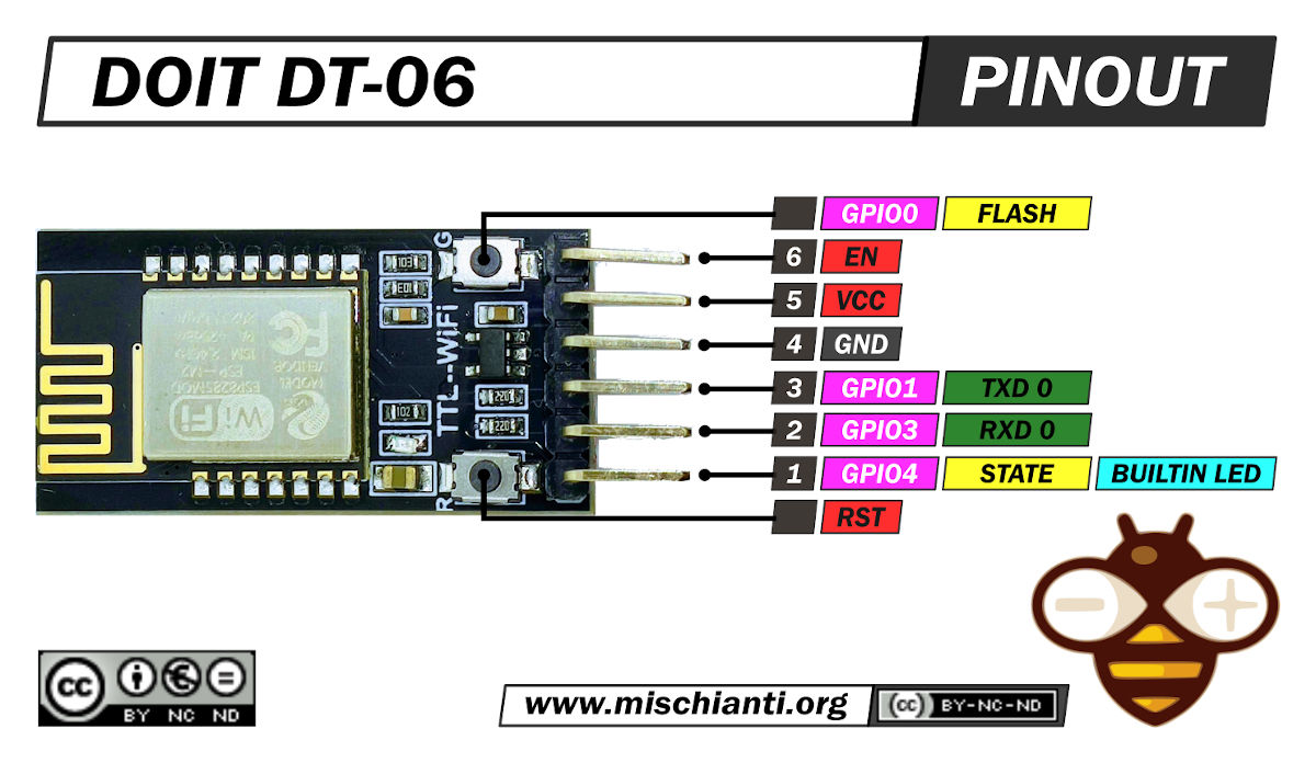
Here the device DT-06
You can find more information in the relative article “DOIT DT-06: high-resolution pinout and specs”.
DT-06 check and upload the latest DOIT Firmware
When I bought the DT-06, It arrived with old firmware with some bugs. I started to search and update the firmware in the DOIT site forum. I found the latest version, but the firmware with home kit integration and other firmware features is on Baidu Drive, and I can’t download It.
Instead, the latest DOIT firmware is downloadable from here.
Flash with the latest DOIT firmware
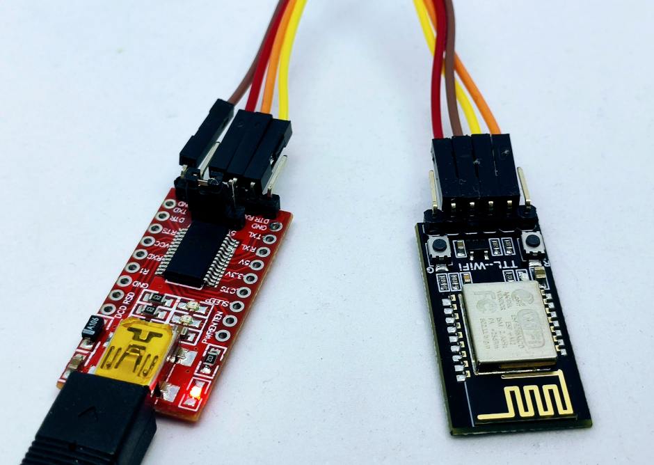
Here the USB to TTL converter USB to TTL CH340G - USB to TTL FT232RL
- First of all, download the DOIT firmware and uncompress It.
- Download the Flash Download Tool from Espressif.
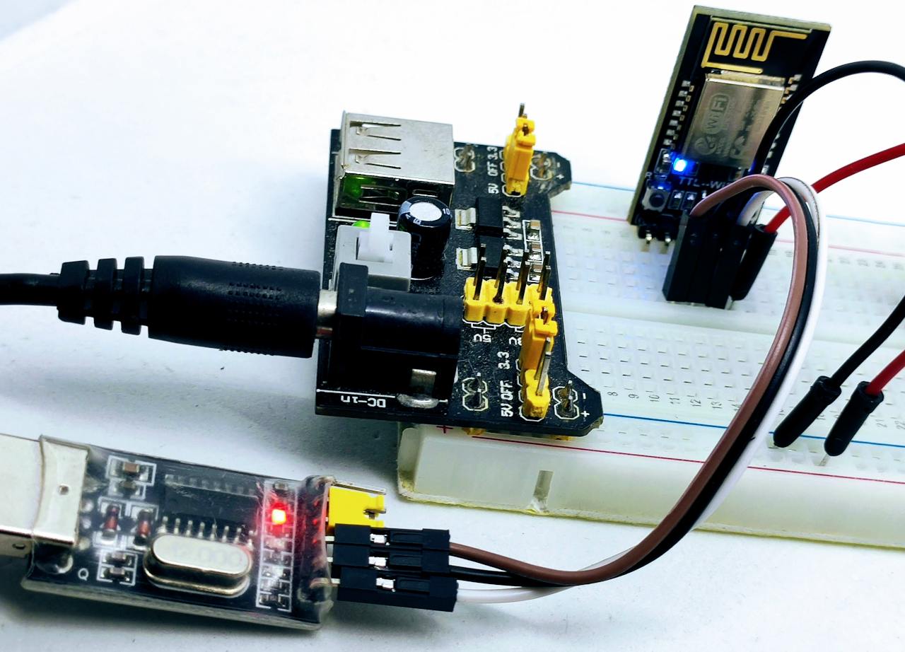
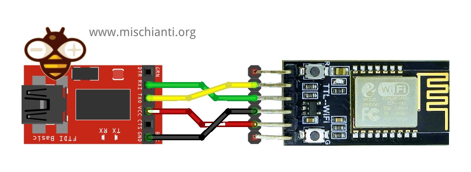
- Wiring the DT-06 to an FTDI USB like so:
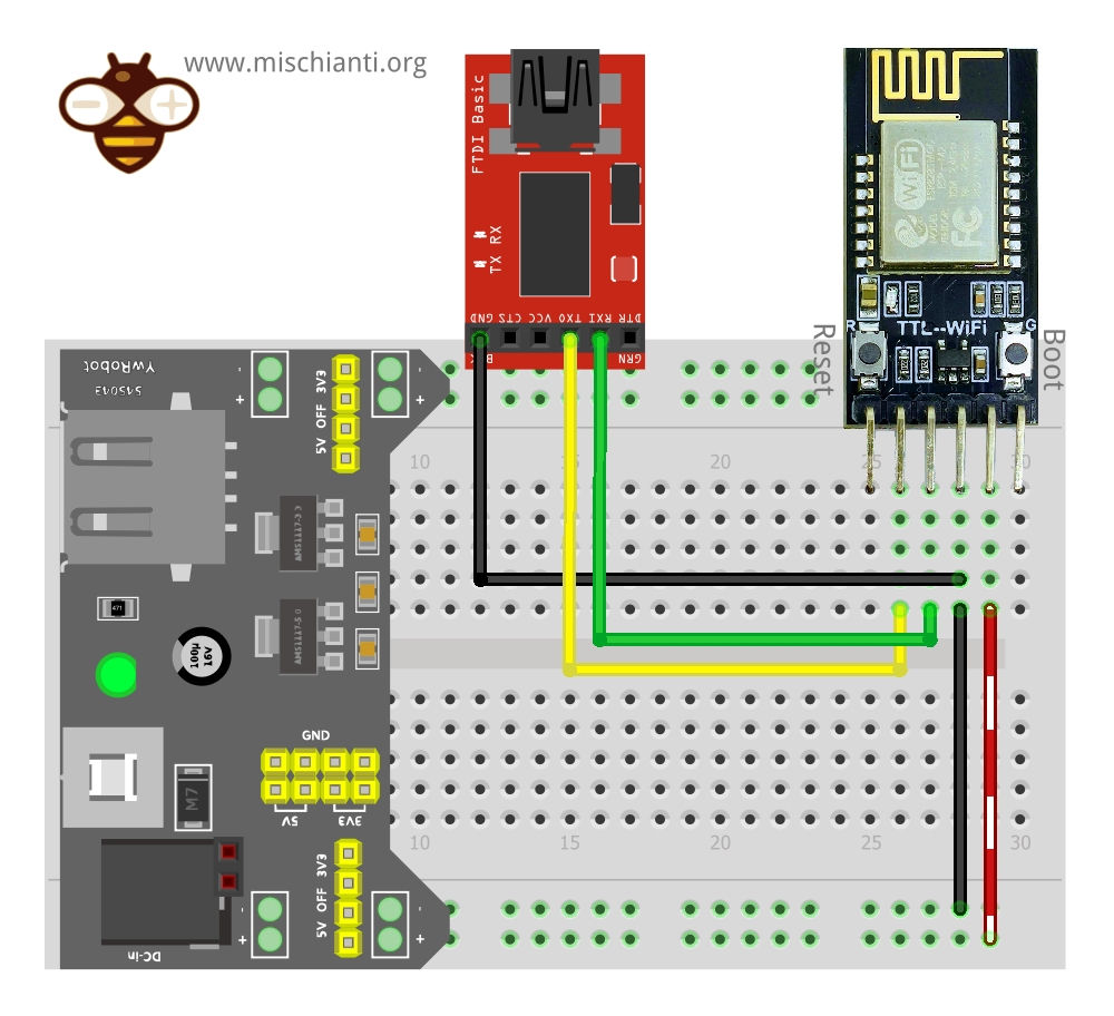
Or with an external power supply like so:
The only notation is that FTDI Rx is connected to Tx of DT-06 and Tx to Rx.
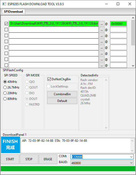
- Now start the Flash Download Tool and open the firmware file, the writing start address is
0x0.
- Put the DT-06 in download mode by following these steps:
- Hold down the Boot button;
- Press and release the Reset button;
- Release the Boot button.
- Click on ERASE.
- Click on the start button.
- Reboot the device.
Configure the DT-06 with the original software
First of all, we are going to check the potentiality of the original firmware of DT-06. It’s a good choice if you need only the Serial debugger to communicate via WiFi to the device.
The device starts in AP mode. If you check over the WiFi network, you find one with a name like Doit_WiFi_XXXXXX. You can connect to that and then go to the address 192.168.4.1.
For the first configuration, I use the phone without touching my PC.
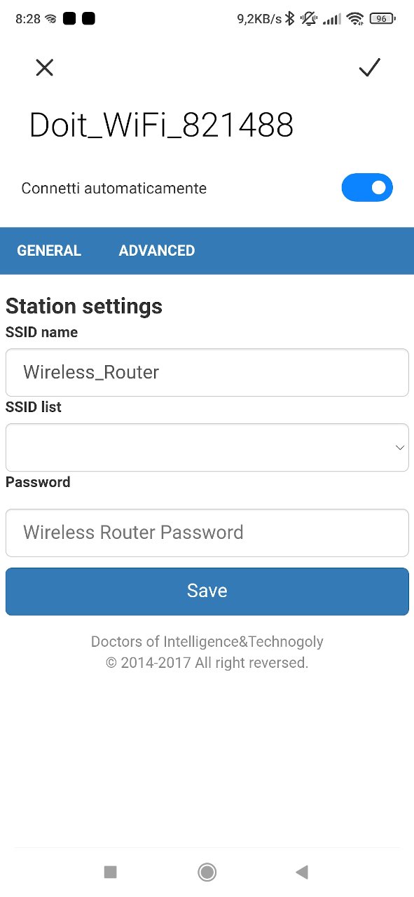
In the first screen, I add my SSID and password, then I restart the device and reconnect via AP mone.
When I enter now, I can see my SSID stored, if you go to the ADVANCED menu, you can see the IP given from the DHCP server.
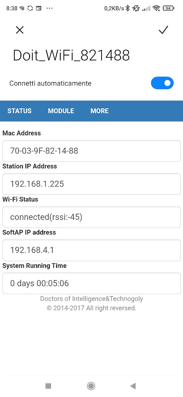
To simplify the next steps, I advise setting a static IP, go to ADVANCED -> MODULE -> WiFi.
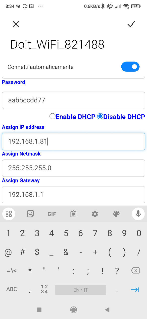
And remember to save the changes.
Wiring to Arduino for remote debug
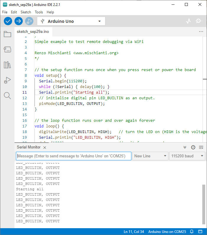
First of all, upload a simple sketch to Arduino. Here is an example:
/*
Simple example to test remote debugging via WiFi

Renzo Mischianti <www.mischianti.org>
*/

// the setup function runs once when you press reset or power the board
void setup() {
  Serial.begin(115200);
  while (!Serial) { delay(100); }
  Serial.println("Starting all");
  // initialize digital pin LED_BUILTIN as an output.
  pinMode(LED_BUILTIN, OUTPUT);
}

// the loop function runs over and over again forever
void loop() {
  digitalWrite(LED_BUILTIN, HIGH);   // turn the LED on (HIGH is the voltage level)
  Serial.println("LED_BUILTIN, HIGH");
  delay(1000);                       // wait for a second
  digitalWrite(LED_BUILTIN, LOW);    // turn the LED off by making the voltage LOW
  Serial.println("LED_BUILTIN, LOW");
  delay(1000);                       // wait for a second
}
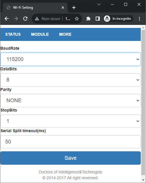
As you can see, I use 115200 as the Serial baud rate, and we are going to set the same value on the DT-06 web interface. In the Web Interface, go to MODULE -> SERIAL.
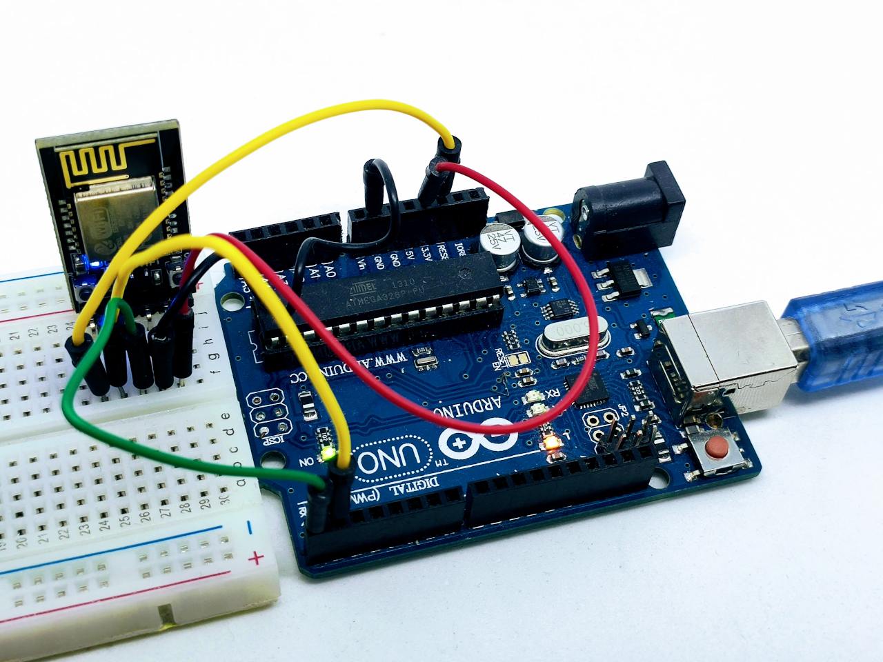
Now the microcontroller is ready, we can go to wire the DT-06.
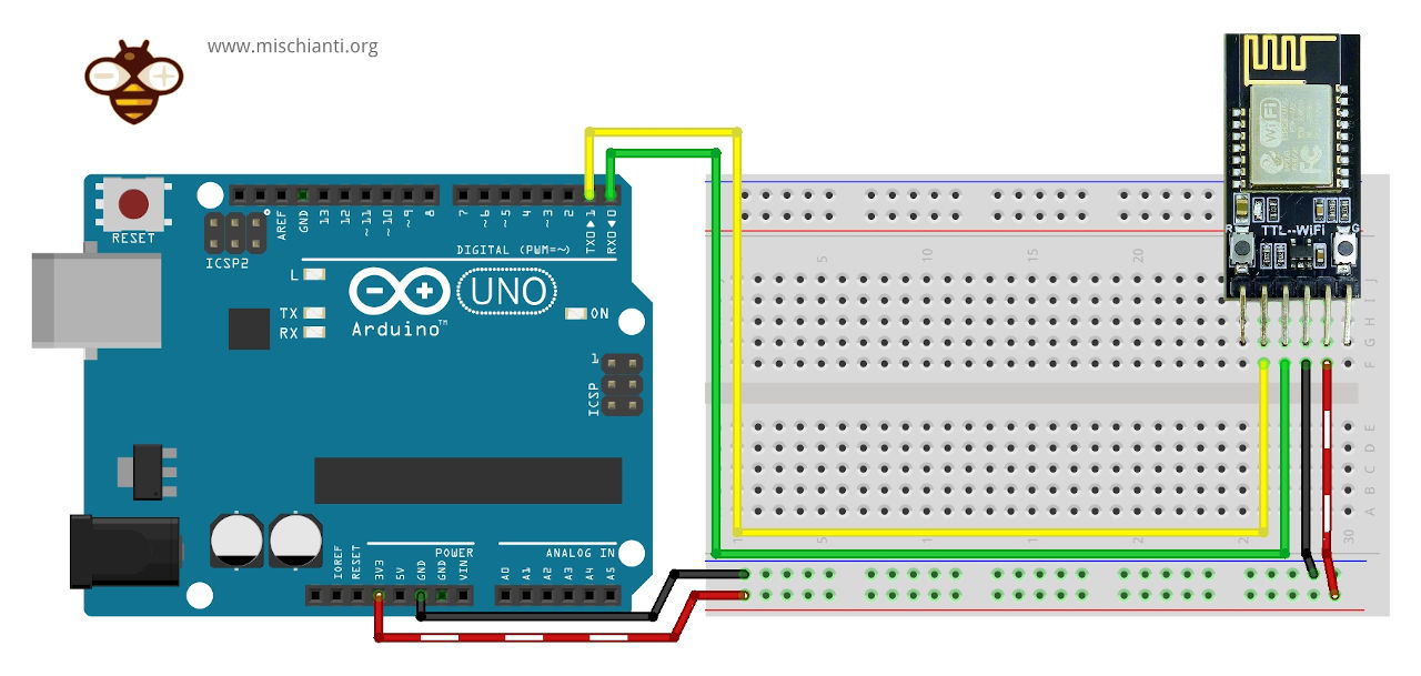
You can see that the Rx of DT-06 is connected to the Tx of Arduino and vice-versa for the Tx of DT-06 and Rx of the Arduino.
DT-06 has 3.3v logic, so when you connect to the Arduino UNO for long operations, It’s better to put a logic converter of a simple voltage divider like so.
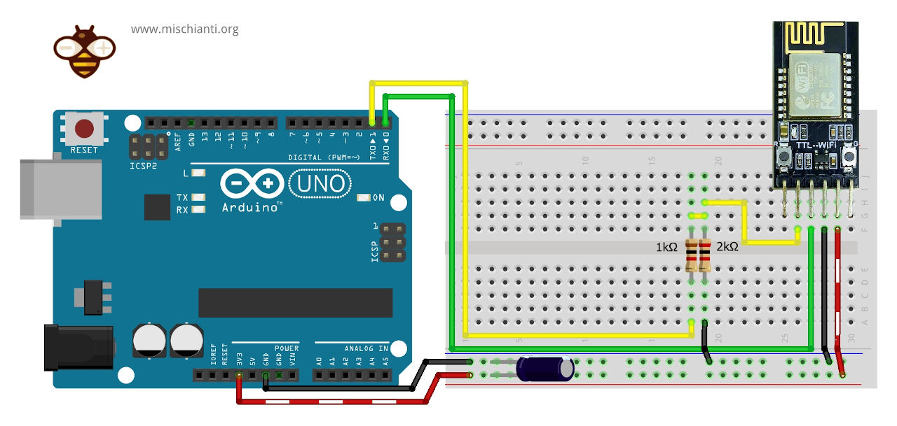
The voltage divider is explained in the article “Voltage divider: calculator and application” with the relative calculator.
You can see that I added the divider only to the line from Tx of Arduino and Rx of DT-06 because this is the only line that works (from Arduino) at 5v, for the vice-versa, Arduino has sufficient sensibility to read at 3.3v logic level.
Create a virtual COM port
Now, we have an interface that communicates via WiFi to our device, but how do we connect to It? A versatile and beautiful system is to generate a virtual COM port.
One of the most used programs is “HW VSP3 – Virtual Serial Port”, you can download from this page, download the single one because the multi is a payment product.
After downloading, install It.
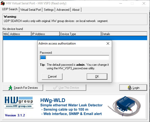
Click the Login button and write admin as password.
You need to retrieve all the parameters from the esp8285 web interface.
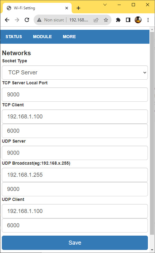
In this case, the port that interests you is the 9000, and you get the IP from the previous screen (if you set the static IP, It’s better).
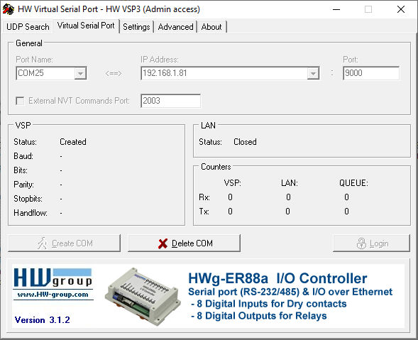
In the Virtual Serial Port tab, choose the COM port number, insert the IP address and the port 9000. After that, click the button Create COM.
Wait a moment, and if It’s okay in the Device Manager, you can find your new Port.
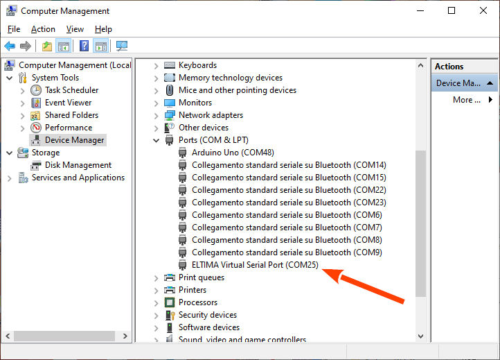
Now, if we connect our Arduino IDE to the Serial COM port 25, we can transmit and receive the Serial via WiFi.
Thanks
- Arduino Remote/wireless Programming
- BMP280, DHT11 and DHT22, DHT12, Dallas Temperature ds18b20, Thermistor
- ATtiny Programmer Board (ArduinoUNO As ISP)
- Send email with esp8266 and Arduino (Library v1.x)
- How to use SD card with esp8266 and Arduino
- Ebyte LoRa E32 device for Arduino, esp32 or esp8266: WOR (wake on radio) microcontroller and new Arduino shield
- Manage JSON file with Arduino, esp32 and esp8266
- How to interface Arduino, esp8266 or esp32 to RS-485
- Send emails with attachments (v2.x library): Arduino Ethernet
- WebSocket
- Arduino AVR: compiled binary (.hex) from command line and GUI tool
- Arduino: fast external SPI Flash memory
- GY-291 ADXL345 i2c spi accelerometer with interrupt for esp32, esp8266, stm32 and Arduino
- i2c Arduino: how to create network, parameters and address scanner
- GY-273 QMC5883L clone HMC5883L magnetometer for Arduino, esp8266 and esp32
- WiFi remote debugging of an Arduino with DT-06
- Program Arduino UNO Remotely via WiFi with DT-06 ESP-Link Firmware
- Introduction to Remote Programming of Arduino UNO via WiFi with ESP8266
- Remote WiFi debugging on Arduino Using ESP8266 (NodeMCU and ESP01) with ESP-LINK Firmware
- Arduino: manage GPS signal with GY NEO 6M and similar devices