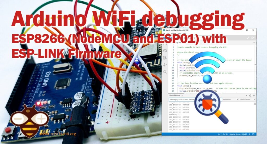
Remote WiFi debugging on Arduino Using ESP8266 (NodeMCU and ESP01) with ESP-LINK Firmware
Remote debugging is an essential feature for any embedded system, including Arduino-based projects. The ESP8266 WiFi module has gained popularity for such applications, especially when used with ESP-LINK firmware. This article aims to guide you through setting up an enhanced remote debugging environment using Arduino, ESP8266 (NodeMCU and ESP01), and ESP-LINK firmware.
What is ESP-LINK Firmware?
ESP-LINK is an open-source firmware that connects a micro-controller to the internet using an ESP8266 WiFi module. It offers a plethora of features:
- Transparent bridge between WiFi and serial, useful for debugging or inputting into a microcontroller (uC).
- Flash-programming attached Arduino/AVR microcontrollers and other ARM microcontrollers via WiFi.
- Outbound REST HTTP requests from the attached micro-controller to the internet.
- MQTT client pub/sub from the attached micro-controller to the internet.
- Serve custom web pages containing data that is dynamically pulled from the attached uC.
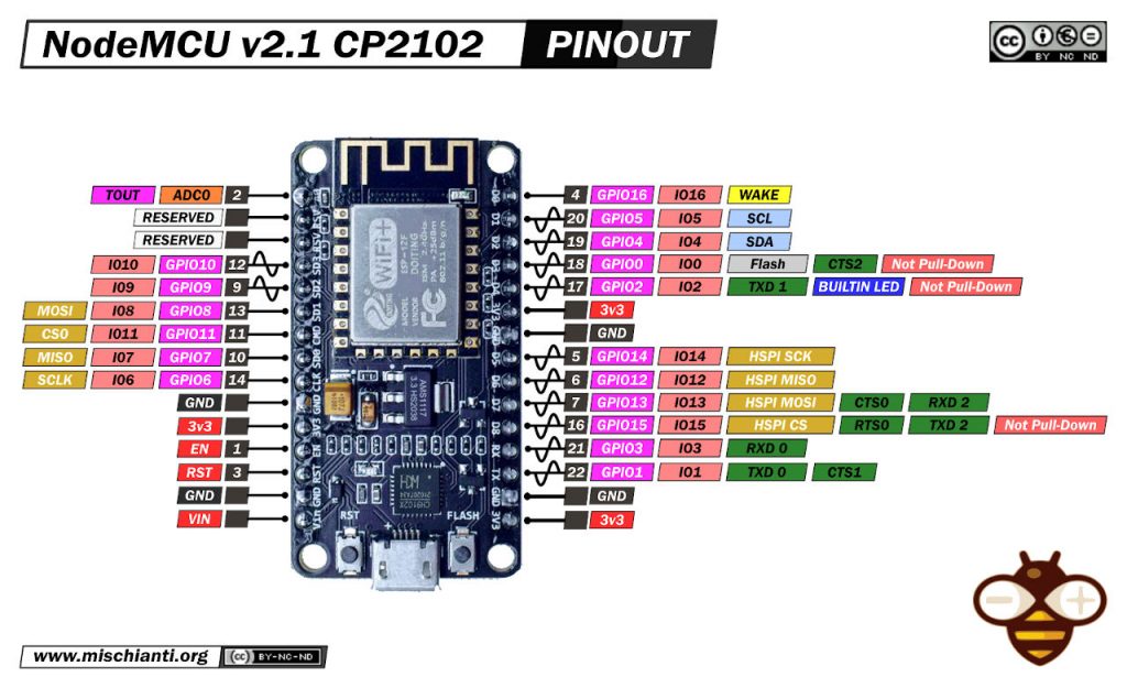
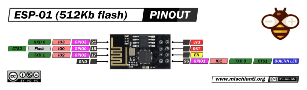
WiFi Module
Before we delve into the nitty-gritty of flashing firmware and setting up remote debugging, let’s take a moment to look at the devices at the heart of this article:
esp8266
For this test, I use a NodeMCU; in this case, the firmware must be the ESP-LINK, so first of all, we must upload that.
For the production version, I advise the ESP-01 described in this old article of the site “ESP-01 modules programming board“.
Upload the ESP-LINK firmware
You can retrieve the latest version of ESP-LINK firmware from here. After the download, uncompress It, and download the Flash Download Tool from Espressif.
Wiring
For the NodeMCU, It’s simple: you must only connect the USB; for the ESP-01, you can follow the extensive guide here, or try these simple steps.
Get an FTDI from the link below.
Here the FTDI USB to TTL CH340G - USB to TTL FT232RL
So you must connect the device to the ESP-01 like so.
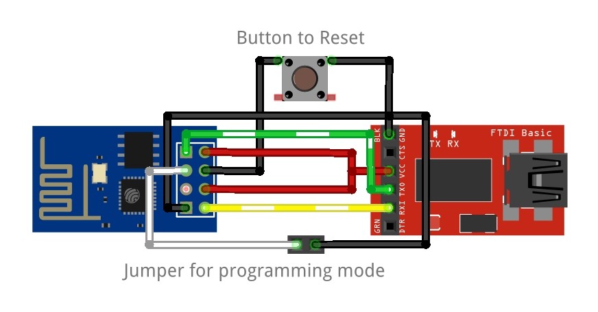
Now, to program, use the jumper of programming mode and click the reset button.
Flash the device
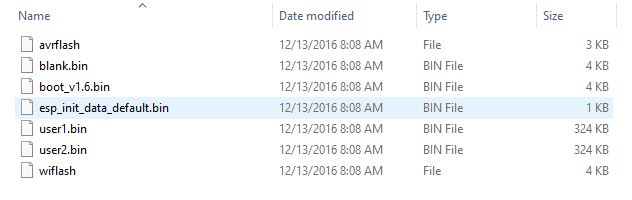
In the firmware folder, you can find these files
File description
boot_v1.6.bin
Description: This is the bootloader file responsible for initializing the hardware and loading the main firmware. It is the first code that runs when the device starts up. The version number (v1.7 in this case) indicates the bootloader’s version.
user1.bin
Description: This is the main application firmware, containing the compiled source code and assets required for the device’s specific functions. It gets loaded by the bootloader and takes over the main operation of the device. The “user1” designation generally indicates that this is the primary application space; in some configurations, a “user2.bin” could also exist for backup or alternate firmware.
esp_init_data_default.bin
Description: This file contains default initialization data for the ESP device. It is typically used to set default system configurations, including settings for the RF module, Wi-Fi parameters, and other hardware-related values.
blank.bin
Description: This file is usually filled with empty (zero) data and is used to clear or reset specific sectors of the flash memory. This is useful when upgrading firmware or when you need to ensure that no residual data remains in these memory areas.
The firmware adapts to the size of the flash chip using information stored in the boot sector (address 0). This is the standard way that the esp8266 SDK detects the flash size. What this means is that you need to set this properly when you flash the bootloader. If you use esptool.py you can do it using the -ff and -fs options. See the end of this page for instructions on installing esptool.py.
Addresses of 32mbit Flash Memory (4MB)
Device like NodeMCU, WeMos D1 mini and other use these settings.
| Address | File Name | Size (MB) |
|---|---|---|
| 0x00000 | boot_v1.6.bin | 0.5 |
| 0x01000 | user1.bin | 3.5 |
| 0x3FC000 | esp_init_data_default.bin | 0.1 |
| 0x3FE000 | blank.bin | 0.1 |
Here is an example of an upload with esptool.py:
esptool.py --port /dev/ttyUSB0 --baud 230400 write_flash -fs 32m -ff 80m \
    0x00000 boot_v1.6.bin 0x1000 user1.bin \
    0x3FC000 esp_init_data_default.bin 0x3FE000 blank.bin
Addresses of 16mbit Flash Memory (2MB)
Some devices, like the updated DT-06, can use these settings.
| Address | File Name | Size (MB) |
|---|---|---|
| 0x00000 | boot_v1.6.bin | 0.5 |
| 0x01000 | user1.bin | 1.8 |
| 0x1FC000 | esp_init_data_default.bin | 0.1 |
| 0x1FE000 | blank.bin | 0.1 |
Addresses of 8mbit Flash Memory (1MB)
ESP-01S and some versions of DT-06 use these settings.
| Address | File Name | Size (MB) |
|---|---|---|
| 0x00000 | boot_v1.6.bin | 0.5 |
| 0x01000 | user1.bin | 0.9 |
| 0xFC000 | esp_init_data_default.bin | 0.1 |
| 0xFE000 | blank.bin | 0.1 |
Addresses of 4mbit Flash Memory (512Kb)
Original DT-06, ESP-01, and other little devices need these settings.
| Address | File Name | Size (MB) |
|---|---|---|
| 0x00000 | boot_v1.6.bin | 0.5 |
| 0x01000 | user1.bin | 0.4 |
| 0x7C000 | esp_init_data_default.bin | 0.1 |
| 0x7E000 | blank.bin | 0.1 |
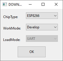
With the Flash download tool, it’s quite simple. When you start Flash Download Tool you must select esp8266 and then start to configure It.
Here is an example of a configuration for the NodeMCU
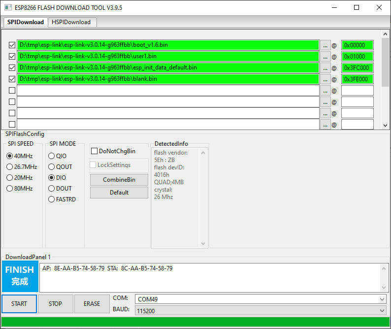
First of all, I execute an ERASE.
Uploading stub...
Running stub...
Stub running...
Changing baud rate to 115200
Changed.
crc_efuse_4bit: 0
crc_calc_4bit: 6
Then, I proceed to the flash.
Uploading stub...
Running stub...
Stub running...
Changing baud rate to 115200
Changed.
NO XMC flash  detected!
crc_efuse_4bit: 0
crc_calc_4bit: 6
Flash will be erased from 0x00000000 to 0x00000fff...
Flash will be erased from 0x00001000 to 0x00051fff...
Flash will be erased from 0x003fc000 to 0x003fcfff...
Flash will be erased from 0x003fe000 to 0x0044efff...
Compressed 3856 bytes to 2763...
Compressed 330756 bytes to 244619...
Compressed 128 bytes to 75...
Compressed 330756 bytes to 244619...

 is stub and send flash finish
After resetting, we can go to configure the device.
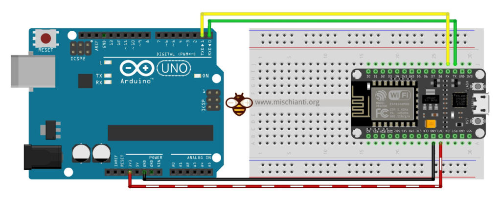
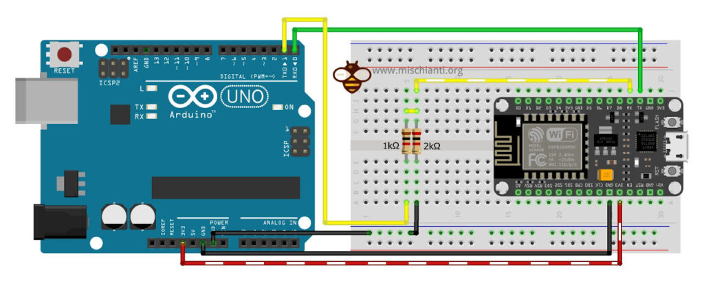
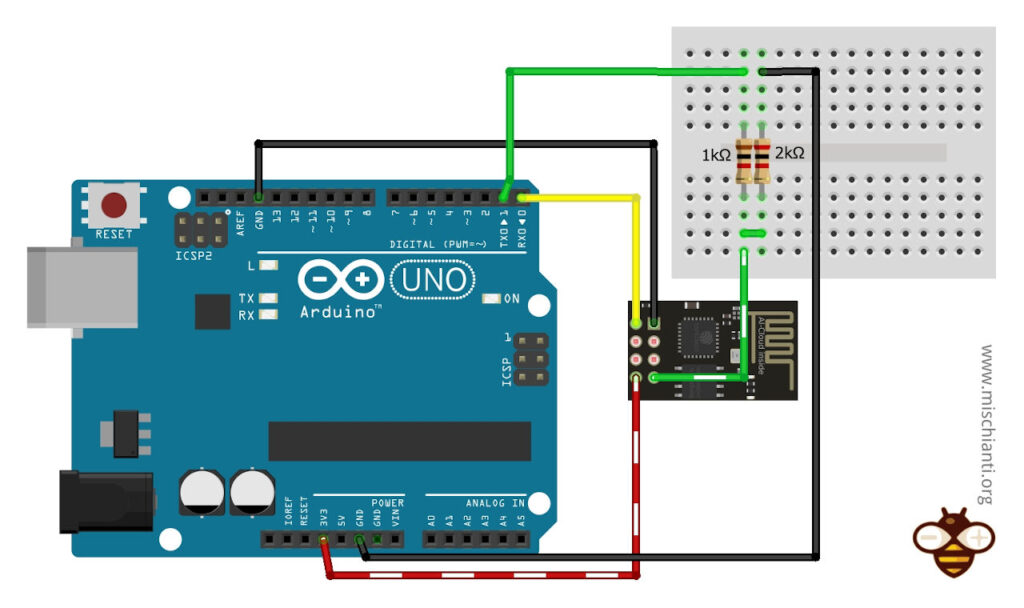
ESP-LINK wiring
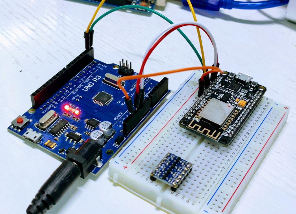
Arduino UNO to NodeMCU
First of all, we must specify that this is the basic connection only for debugging, not for programming, and we must consider that Arduino UNO has a 5v logic level and NodeMCU 3.3v.
To do that, we need only the power supply and Rx and Tx connect.
In this configuration, in case of long-time transmission, It’s possible to fire the esp8266, so I advise using a simple voltage divider from Tx of Arduino UNO to Rx of NodeMCU.
ESP-01 to Arduino UNO
Similar connection schema for ESP-01
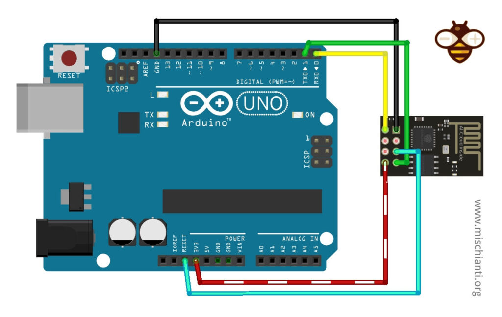
Here with voltage divider.
ESP-LINK configuration
Setting up the ESP-Link firmware on the ESP8266 module is a straightforward process, but for those unfamiliar, it can seem daunting. The firmware provides a user-friendly interface to configure the ESP8266, turning it into a versatile WiFi bridge. The following step-by-step guide, accompanied by screenshots for each phase, aims to simplify this process, ensuring a smooth and error-free setup for users of all levels of expertise.
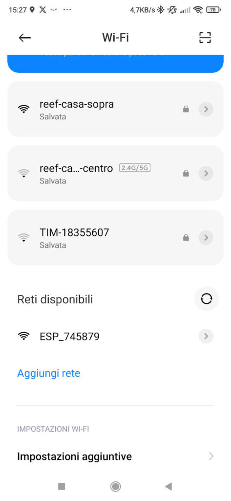
Connecting to ESP Network
In this screenshot, you can see a list of available WiFi networks on a device. Prominently displayed is the ESP_XXXXXX network. This represents the Access Point (AP) mode of the ESP8266, which becomes active after the installation of the esp-link firmware. The user is advised to select this specific network to initiate the configuration process.
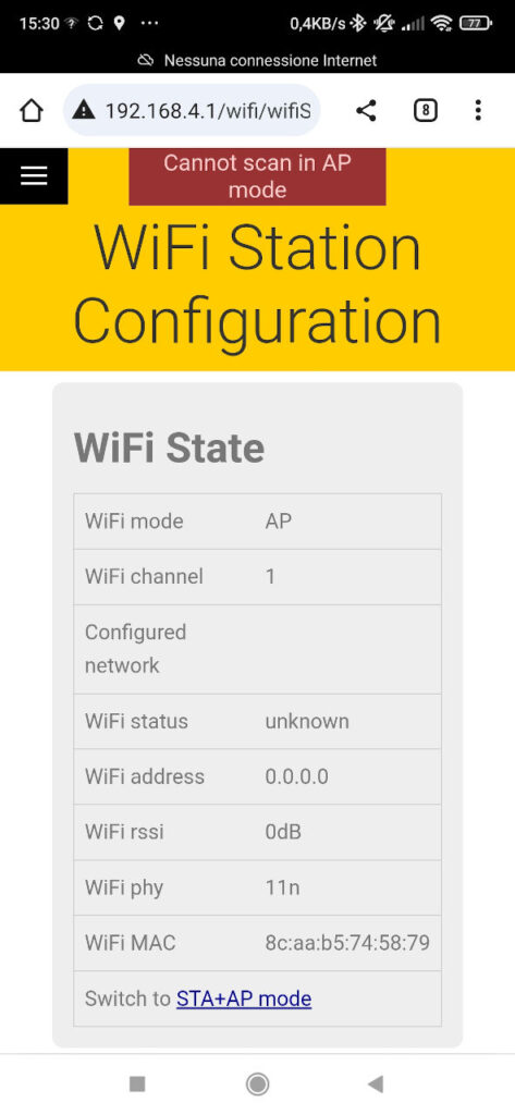
Main ESP-Link Page
Upon accessing the IP 192.168.4.1, the screenshot displays the main interface of the esp-link page. The central portion of the screen shows the current WiFi state. At the top, there’s a noticeable message stating that the device cannot perform scanning while in AP mode. This message serves as a reminder of the device’s current operational mode.
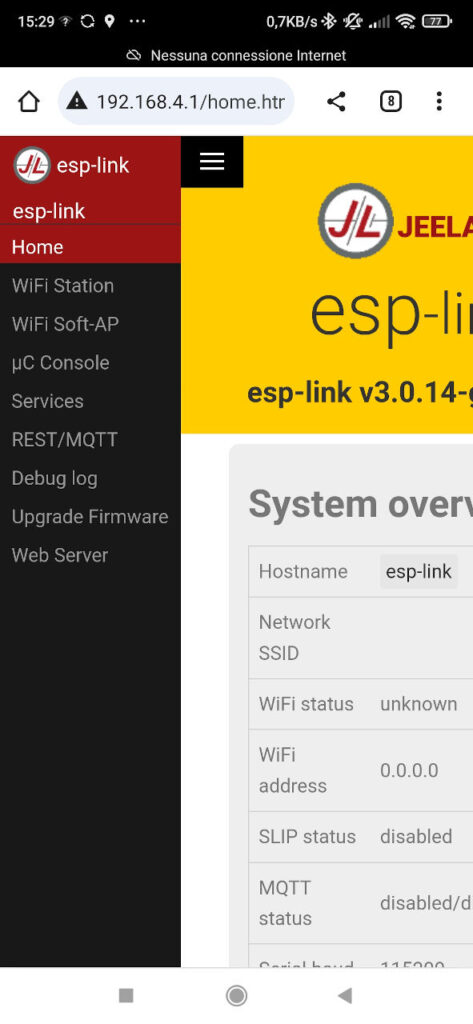
Navigating to WiFi Station Settings
This screenshot showcases the main esp-link page but with an expanded left-side menu. Among the various options, the WiFi station link is highlighted, indicating that the user has clicked or is about to click on it to access the WiFi station settings.
Switching to STA+AP Mode
The focus of this screenshot is the WiFi Station configuration interface. A prominent link labeled Switch to STA+AP mode is displayed. This option allows users to enable both the Station (STA) and Access Point (AP) modes simultaneously. The user is prompted to click this link to proceed.
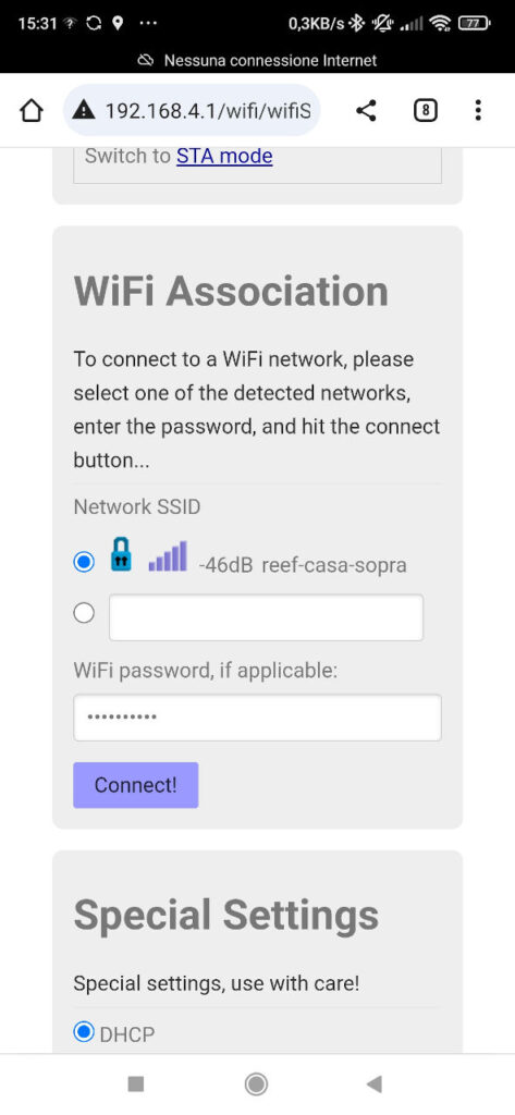
Selecting a WiFi Network
In this phase, the screenshot reveals a list of available WiFi networks within the WiFi Station configuration screen. Users are guided to select their preferred network from this list. Adjacent to each network name is a field to input the network’s password. After entering the password, there’s a connect button to establish the connection.
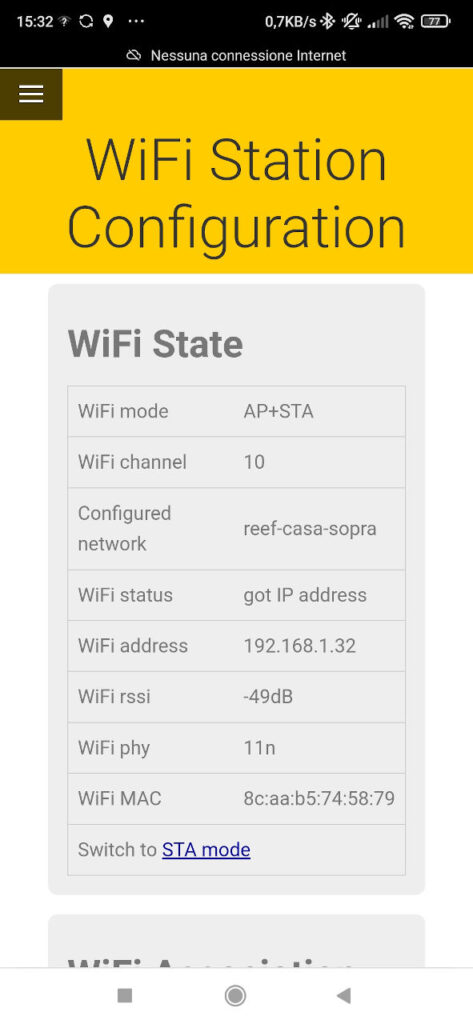
Returning to the Main Page with DHCP IP
After connecting to a WiFi network, the screenshot returns the user to the main esp-link page at 192.168.4.1. The AP mode remains active, but now there’s an additional piece of information: the IP address assigned by the DHCP server. This IP is crucial for subsequent steps.
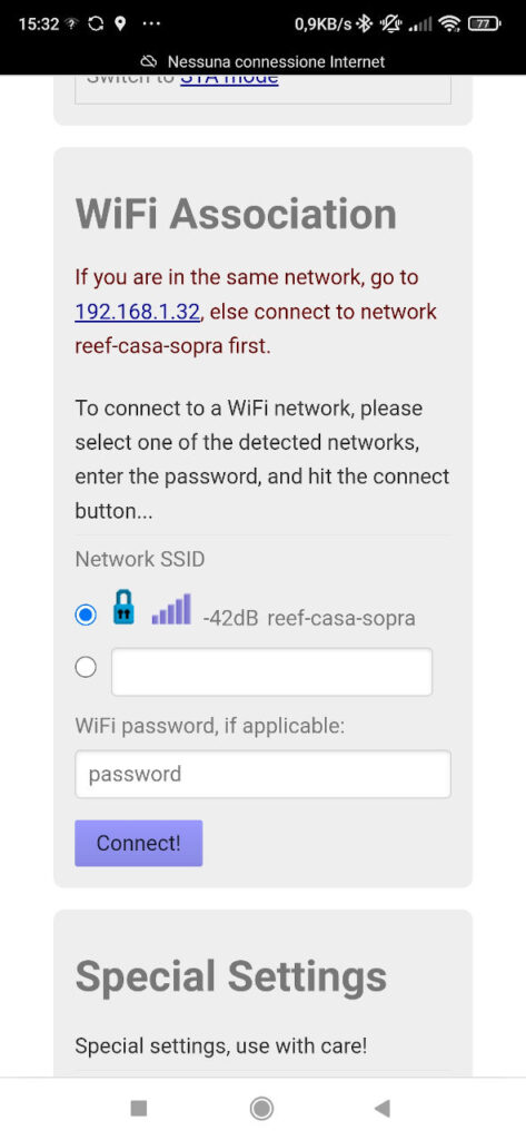
WiFi Station Screen with Connection Guidance
This screenshot of the WiFi Station screen provides users with clear instructions. A message informs users that if their device is on the same network, they should navigate directly to the IP address provided by the DHCP. If not, the first step is to connect to the network with the specified SSID.
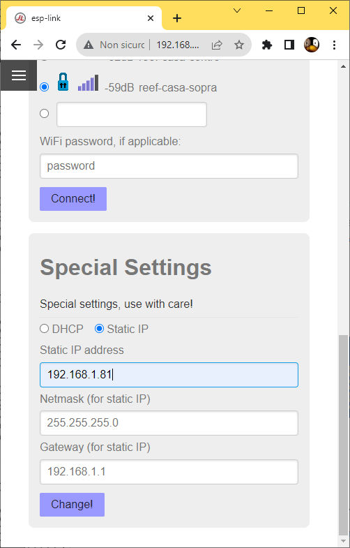
Setting a Static IP
The final screenshot guides users on setting a static IP for their device. After connecting via the DHCP-assigned IP and accessing the WiFi station settings, users can scroll down to find an option to set a static IP. This feature ensures the device will always have the same IP address, making it easier to connect in the future.
Upload test code to Arduino
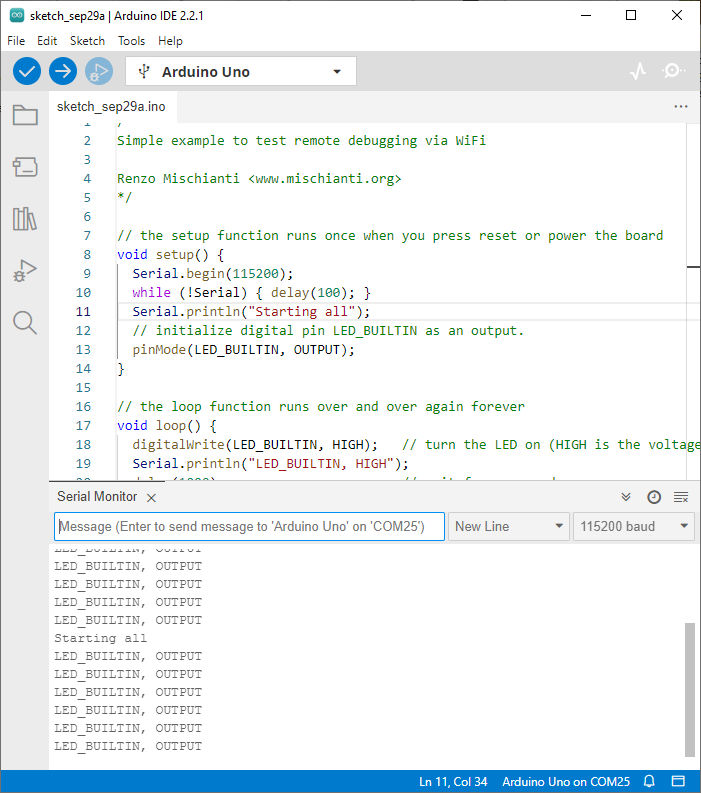
For this test, I wrote a simple sketch and uploaded It on Arduino.
/*
Simple example to test remote debugging via WiFi

Renzo Mischianti <www.mischianti.org>
*/

// the setup function runs once when you press reset or power the board
void setup() {
  Serial.begin(115200);
  while (!Serial) { delay(100); }
  Serial.println("Starting all");
  // initialize digital pin LED_BUILTIN as an output.
  pinMode(LED_BUILTIN, OUTPUT);
}

// the loop function runs over and over again forever
void loop() {
  digitalWrite(LED_BUILTIN, HIGH);   // turn the LED on (HIGH is the voltage level)
  Serial.println("LED_BUILTIN, HIGH");
  delay(1000);                       // wait for a second
  digitalWrite(LED_BUILTIN, LOW);    // turn the LED off by making the voltage LOW
  Serial.println("LED_BUILTIN, LOW");
  delay(1000);                       // wait for a second
}
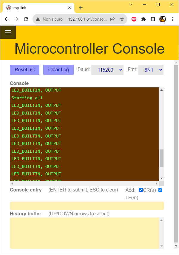
Serial Monitor web interface
The ESP-LINK Web interface offers a practical console to explore and interact with the serial.
Add a virtual COM port
The ESP-LINK firmware is a powerful tool that transforms an ESP8266 module into a transparent WiFi bridge, enabling seamless communication between devices. One of its standout features is the ability to create a virtual COM port, allowing users to communicate with serial devices over a WiFi network remotely. This capability is especially valuable for those looking to integrate traditional serial devices into modern IoT ecosystems without the constraints of physical connections.
For this purpose, I use HW VSP3 (Hardware Virtual Serial Port), which is a software solution that allows you to create and manage virtual COM ports on your computer, you can download from this page, download the single one because the multi is a payment product.
These virtual ports can be linked to real physical serial ports, or they can emulate the behavior of ports that don’t physically exist. This is especially useful for software development, testing, and debugging purposes.
After downloading, install It.
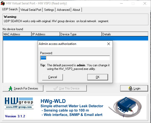
Click the Login button and write admin as password.
You need to retrieve all the parameters from the ESP-LINK web interface.
In this case, the port that interests you is the 23, and you get the IP from the previous screen (if you set the static IP, It’s better).
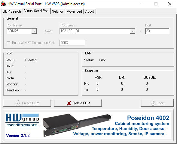
In the Virtual Serial Port tab, choose the COM port number and insert the IP address and port 23. After that, click the button Create COM.
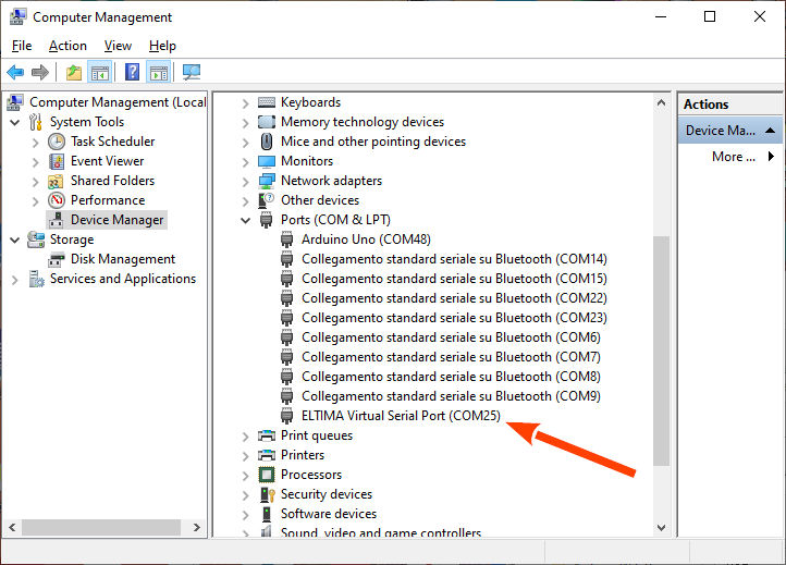
Wait a moment; if It’s okay in the Device Manager, you can find your new Port.
Now, if we connect our Arduino IDE to the Serial COM port 25, we can transmit and receive the Serial via WiFi.
Thanks
- Arduino Remote/wireless Programming
- BMP280, DHT11 and DHT22, DHT12, Dallas Temperature ds18b20, Thermistor
- ATtiny Programmer Board (ArduinoUNO As ISP)
- Send email with esp8266 and Arduino (Library v1.x)
- How to use SD card with esp8266 and Arduino
- Ebyte LoRa E32 device for Arduino, esp32 or esp8266: WOR (wake on radio) microcontroller and new Arduino shield
- Manage JSON file with Arduino, esp32 and esp8266
- How to interface Arduino, esp8266 or esp32 to RS-485
- Send emails with attachments (v2.x library): Arduino Ethernet
- WebSocket
- Arduino AVR: compiled binary (.hex) from command line and GUI tool
- Arduino: fast external SPI Flash memory
- GY-291 ADXL345 i2c spi accelerometer with interrupt for esp32, esp8266, stm32 and Arduino
- i2c Arduino: how to create network, parameters and address scanner
- GY-273 QMC5883L clone HMC5883L magnetometer for Arduino, esp8266 and esp32
- WiFi remote debugging of an Arduino with DT-06
- Program Arduino UNO Remotely via WiFi with DT-06 ESP-Link Firmware
- Introduction to Remote Programming of Arduino UNO via WiFi with ESP8266
- Remote WiFi debugging on Arduino Using ESP8266 (NodeMCU and ESP01) with ESP-LINK Firmware
- Arduino: manage GPS signal with GY NEO 6M and similar devices
- Arduino UNO/Mega and Ethernet: Sending Emails with Attachments (EMailSender v4.0.0 Library)
- How to Build an Arduino FTP Server: UNO/Mega, Ethernet & SD (SimpleFTPServer v3.x)
- HC-SR04 Ultrasonic Sensor with ESP32 and Arduino: Complete Guide
- Fix slow HC-SR04 sensors with PCF8574: the hybrid approach trick [Guide]