EByte RF E70 CC1310: exploring library (esp32, esp8266, STM32, Arduino, Raspberry Pi Pico)
The advent of RF long-range technology has revolutionized wireless communication, offering a blend of long-range capabilities and low power consumption. The EByte RF E70 module stands out as a prominent player among the various emerging modules. This article delves into the features, applications, and operational modes of the EByte E70, providing insights into its capabilities and potential uses.
The E70 is based on CC1310 series device. This device is not just a microcontroller (MCU); it is a fully integrated wireless MCU designed specifically for low-power, long-range wireless applications. The CC1310 combines a powerful ARM Cortex-M3 processor with a highly efficient sub-1 GHz radio, making it an ideal solution for a wide range of applications, from smart metering to industrial automation and environmental monitoring.
Introduction to EByte RF E70
The EByte E70 is an RF module designed for long-range wireless communication. It operates in the sub-gigahertz frequency bands, making it ideal for various applications that require long-range communication and low power consumption. Its versatility and efficiency have made it a popular choice in IoT (Internet of Things) applications, smart city projects, and industrial automation.
Key Features of the EByte E70
- Long-Range Communication: The E70 module is known for its exceptional range, capable of transmitting data over several kilometers, depending on environmental conditions.
- Low Power Consumption: It’s optimized for low power usage, extending the battery life of devices, which is crucial for IoT applications.
- Multiple Operation Modes: The E70 supports various modes like transparent mode, fixed mode, continuous mode, and sub-package mode, offering flexibility in different use cases.
- Configurable Parameters: Users can configure parameters like frequency, power output, and data rate, making them adaptable to various communication needs.
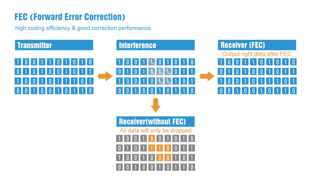
- Forward Error Correction (FEC): FEC is a method for error control in data transmission. It adds redundancy to the transmitted information using a predetermined algorithm. This redundancy allows the receiver to detect and correct errors without the need for retransmission.
Device specifications
- The communication distance tested is up to 1.5/6km
- Maximum transmission power of 1W, software multi-level adjustable;
- Support air date rate of 2.5kbps~168kbps;
- Low power consumption for battery-supplied applications;
- Can achieve up to 115200bps continuous frame unlimited-packet length transmission
- E70-xxxT30S Support 2.6 ~ 5.5V power supply, more than 5V power supply to ensure the best performance;
- E70-xxxT14S/S2 support 2.2 ~ 3.8V power supply, more than 3.3V power supply to ensure the best performance;
- Industrial grade standard design, support -40 ~ 85 °C for working over a long time;
- Support high-speed continuous transmission, send and receive unlimited data packet length;
- Support continuous data frame without packetization, perfect support for ModBus protocol;
- Support custom subcontracting settings to improve communication efficiency;
- Support fixed-point transmission/broadcast transmission/channel monitoring;
- Support RSSI signal strength reading;
- Support over-the-air wake-up, i.e. low-power function, suitable for battery-powered solutions;
- Developed based on CC1310 chip, built-in dual-core ARM;
- Ultra-small volume design;
- Ultra-low receiving current, only about 8mA;
- E70-433 T30S maximum transmit power of 30dBm, the other three models are 25mW, softwaremulti-level adjustable;
- Under ideal conditions, the communication distance can reach 1.5km;
- E70-433T30S built-in PA+LNA, transmission power 1W, communication distance up to 6km;
- Supports the global license-free ISM 433MHz band;
- Support 2.5K~168kbps air transmission rate;
- Support 2.2~3.8V power supply, greater than 3.3V power supply can ensure the best performance;
- E70-433T30S supports 2.6~5.5V power supply , morethan 5V power supply can ensure the best performance;
- Dual antenna optional (IPEX/stamp hole) is convenient for users to develop and facilitate integration.
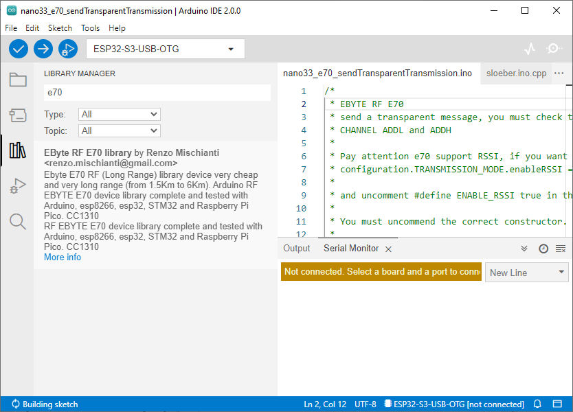
Library installation
You can find the library on GitHub.
But for simplicity, I added it to the Arduino Library manager.
RF E70 variants
E70 has various form factors, the design changes, and also specifications.
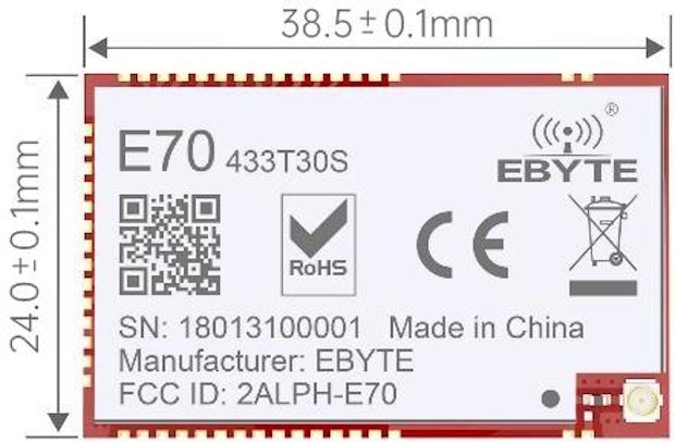
E70-433T30S:
- Logic level voltage: 3.3v and 5v support
- Transmit Power: 30dBm (higher power, capable of longer-distance transmission)
- Receive Sensitivity: -107 to -109 dBm
- Reference Distance: 6000m
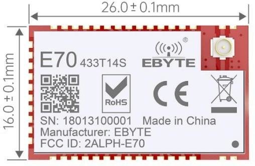
E70-433T14S:
- Logic level voltage: only 3.3v
- Transmit Power: 14dBm (lower power compared to the T30S)
- Receive Sensitivity: -109 to -111 dBm for T14S and -108 dBm for T14S2 (slightly better sensitivity for the T14S)
- Reference Distance: 1500m
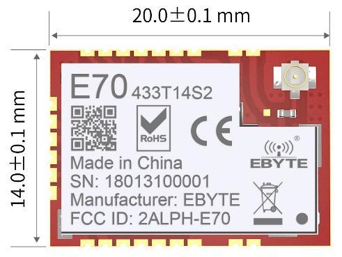
E70-433T14S2:
- Logic level voltage: only 3.3v
- Update of S version.
- Receive Sensitivity: -109 to -111 dBm for T14S and -108 dBm for T14S2 (slightly better sensitivity for the T14S)
- Form factors are simpler to manage.
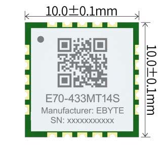
E70-433MT14S:
- Logic level voltage: only 3.3v
- Transmit Power: 14dBm (same as T14S and T14S2)
- Receive Sensitivity: -108 dBm (same as T14S2)
- Reference Distance: 1500m (same as T14S and T14S2)
RF Parameters
| RF parameters | Unit | Model | Remark | |||
|---|---|---|---|---|---|---|
| E70-433T30S | E70-433T14S | E70-433T14S2 | E70-433MT14S | |||
| Transmit power | dBm | 30 | 14 | 14 | 14 | |
| Receive sensitivity | dBm | -107~-109 | -109~-111 | -108 | -108 | The air rate is 2.5kbps |
| Reference distance | M | 6000m | 1500m | 1500m | 1500m | The probability of burning is less when used at close range |
| 5dBi, antenna height 2.5meters, air rate 2.5kbps | ||||||
| Operating frequency band | MHz | 425~450.5 | The factory default is 433MHzand supports the ISM band | |||
| Air velocity | bps | 2.5k~168k | User programmatic control | |||
Blocking power | dBm | 10 | See Transfer Modes for details. | |||
| Launch length | / | The transmission mode is specified | See Transfer Modes for details | |||
Electrical parameter
| Instantaneous power consumption | Unit | Model | Remark | ||||
| E70-433T30S | E70-433T14S | E70-433T14S2 | E70-433MT14S | ||||
| Operating voltage | V | 2.6~5.5 | 2.2~3.8 | 2.2~3.8 | 2.2~3.8 | The software shutdown | |
| Communication level | V | 3.3 | Using 5V TTL carries a risk of burnout | ||||
| Power consumption | Emitted current | mA | 530 | 27 | 36 | 32 | Using 5V TTL carries a risk of burnout |
| Receive current | mA | 14 | 8 | 8 | 9 | ||
| Sleep current | μA | 4 | 1 | 1.2 | 1.7 | Instantaneous power consumption | |
| Temperature | The E70-433T30 Spermanently burns modules over 5.5 V, and the other three models permanently burn modules over 3.8 V. | ℃ | -20~+85 | Industrial grade | |||
| Operating temperature | -40~+125 | ||||||
Hardware parameters
| Hardware parameters | Model | Remark | |||
| E70-433T30S | E70-433T14S | E70-433T14S2 | E70-433MT14S | ||
| Chip | CC1310 | ||||
| Cache capacity | 2048 Byte | User defined | |||
| FLASH | 128 KB | ||||
| RAM | 8 KB | ||||
| Kernel | Cortex-M3(MCU)+Cortex-M0(RF) | ||||
| Communication interface | UART serial port | TTL level | |||
| Modulation method | GFSK | ||||
| Encapsulation method | SMD | ||||
| Antenna interface | IPEX/stamp hole | IPEX/stamp hole | IPEX/stamp hole | Stamp holes | The characteristic impedance is about 50 ohms |
| Size | 24*38.5mm | 16*26 mm | 14 * 20 mm | 10*10mm | The E70-433T14S2 does not include SMA |
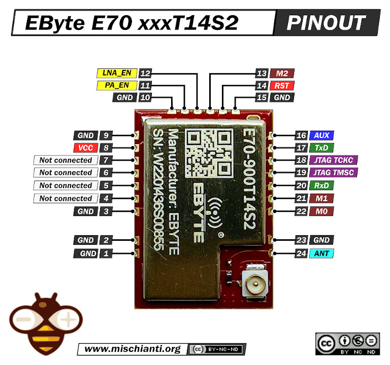
Pinout E70 xxxT14S2
For my test, I’m going to use an E70 S2 version because It’s a comfortable form factor with an onboard SMA antenna.
Connections note
You can find all kinds of wiring diagrams in the previous articles of the series.
As you can see, I also connect the M0, M1, and M2, but these are unnecessary; you can select an operation modality by setting these values to those pins.
| Mode (0-7) | M2 | M1 | M0 | Mode introduction | Remark |
|---|---|---|---|---|---|
| 0 RSSI mode | 0 | 0 | 0 | Module outputs RSSI value each 100ms through UART. | The air data rate can be adjusted automatically according to the baud rate. The baud rate must be the same on both the receiver and transmitter. It is applicable for high-speed continuous data transmission. |
| 1 Continuous mode | 0 | 0 | 1 | UART opens. Wireless closes, and sub-package transparent transmission is available. | UART opens. Wireless closes, and continuous transparent transmission is available. |
| 2 Sub-package mode | 0 | 1 | 0 | UART opens. Wireless closes, and parameters can be configured. | Air data rate and baud rate can be adjusted separately. It is applicable for data packet transmission. |
| 3 Configuration mode | 0 | 1 | 1 | The baud rate is fixed as 9600 8N1. | UART opens. Wireless closes, and subpackage transparent transmission is available. |
| 4 WOR mode | 1 | 0 | 0 | Transmission is not available under this mode. It can be woken up by a transmitter under mode 4 to achieve low power consumption receiving. | Receiving is not available under this mode. Preamble code will be added proactively before transmission to wake up the receiver under mode 6. |
| 5 Configuration mode (Same as Mode 3) | 1 | 0 | 1 | – | – |
| 6 Power saving mode | 1 | 1 | 0 | Any M2, M1, or M0 falling edge can wake it up. | UART closes. Wireless works at WOR power saving mode. Multiple-time grades can be configured. |
| 7 Sleep mode | 1 | 1 | 1 | Any falling edge of M2, M1, or M0 can wake it up. | UART closes, wireless transmitting is available, and sleep mode is on. |
For this experiment, you must set the devices in sub-packet mode.
- M0: LOW
- M1: HIGH
- M2: LOW
Constructor
I made a set of numerous constructors because we can have more options and situations to manage.
		RF_E70(byte txE70pin, byte rxE70pin, UART_BPS_RATE bpsRate = UART_BPS_RATE_9600);
		RF_E70(byte txE70pin, byte rxE70pin, byte auxPin, UART_BPS_RATE bpsRate = UART_BPS_RATE_9600);
		RF_E70(byte txE70pin, byte rxE70pin, byte auxPin, byte m0Pin, byte m1Pin, byte m2Pin, UART_BPS_RATE bpsRate = UART_BPS_RATE_9600);
The first set of constructors is created to delegate Serial and other pins to the library.
txE70pinandrxE70pinare the pins to connect to UART. They are mandatory.auxPinis a pin that checks the operation, transmission, and receiving status (we are going to explain better next), that pin isn’t mandatory; if you don’t set It, I apply a delay to permit the operation to complete itself (with latency, if you have trouble, like freeze device, you must put a pull-up 4.7k resistor or better connect to the device ).m0pin,m1Pinandm2Pinare the pins to change operation MODE (see the table upper); I think these pins in “production” are going to connect directly to HIGH or LOW. Still, for a test, they are helpful for the library to manage.bpsRateis the baud rate of SoftwareSerial is typically 9600 (the only baud rate in programming/sleep mode)
A simple example is
#include "RF_E70.h"

RF_E70 e70ttl(2, 3);  // e70 TX e70 RX
// RF_E70 e70ttl(2, 3, 5, 6, 7);  // e70 TX e70 RX
We can use a SoftwareSerial directly with another constructor
		RF_E70(HardwareSerial* serial, UART_BPS_RATE bpsRate = UART_BPS_RATE_9600);
		RF_E70(HardwareSerial* serial, byte auxPin, UART_BPS_RATE bpsRate = UART_BPS_RATE_9600);
		RF_E70(HardwareSerial* serial, byte auxPin, byte m0Pin, byte m1Pin, byte m2Pin, UART_BPS_RATE bpsRate = UART_BPS_RATE_9600);
The example upper with this constructor can be done like so.
#include <SoftwareSerial.h>
#include "RF_E70.h"

SoftwareSerial mySerial(2, 3); // e70 TX e70 RX
RF_E70 e70ttl(&mySerial);
// RF_E70 e70ttl(&mySerial, 5, 6, 7, 8);
The last set of constructors is to permit an HardwareSerial instead of SoftwareSerial.
		RF_E70(SoftwareSerial* serial, UART_BPS_RATE bpsRate = UART_BPS_RATE_9600);
		RF_E70(SoftwareSerial* serial, byte auxPin, UART_BPS_RATE bpsRate = UART_BPS_RATE_9600);
		RF_E70(SoftwareSerial* serial, byte auxPin, byte m0Pin, byte m1Pin, byte m2Pin, UART_BPS_RATE bpsRate = UART_BPS_RATE_9600);
For esp32, you have three additional constructors to permit to manage pins for HardWare serial.
			RF_E70(byte txE70pin, byte rxE70pin, HardwareSerial* serial, UART_BPS_RATE bpsRate = UART_BPS_RATE_9600, uint32_t serialConfig = SERIAL_8N1);
			RF_E70(byte txE70pin, byte rxE70pin, HardwareSerial* serial, byte auxPin, UART_BPS_RATE bpsRate = UART_BPS_RATE_9600, uint32_t serialConfig = SERIAL_8N1);
			RF_E70(byte txE70pin, byte rxE70pin, HardwareSerial* serial, byte auxPin, byte m0Pin, byte m1Pin, byte m2Pin, UART_BPS_RATE bpsRate = UART_BPS_RATE_9600, uint32_t serialConfig = SERIAL_8N1);
Begin
The begin command is used to startup Serial and pins in input and output mode.
void begin();
in execution is
	// Startup all pins and UART
	e70ttl.begin();
Configuration and method to get information
There are many methods for managing configuration and getting information about the device.
		ResponseStructContainer getConfiguration();
		ResponseStatus setConfiguration(Configuration configuration, PROGRAM_COMMAND saveType = WRITE_CFG_PWR_DWN_LOSE);

		ResponseStructContainer getModuleInformation();
        void printParameters(struct Configuration configuration);
        ResponseStatus resetModule();
Response containers
To simplify the response management, I created a set of containers, which is very useful for managing errors and returning generic data.
ResponseStatus
The ResponseStatus is a status container and has two simple entry points, with this you can get the status code and the description of the status code
	Serial.println(c.getResponseDescription()); // Description of code
	Serial.println(c.code); // 1 if Success
The code is
  E70_SUCCESS = 1,
  ERR_E70_UNKNOWN,	/* something shouldn't happened */
  ERR_E70_NOT_SUPPORT,
  ERR_E70_NOT_IMPLEMENT,
  ERR_E70_NOT_INITIAL,
  ERR_E70_INVALID_PARAM,
  ERR_E70_DATA_SIZE_NOT_MATCH,
  ERR_E70_BUF_TOO_SMALL,
  ERR_E70_TIMEOUT,
  ERR_E70_HARDWARE,
  ERR_E70_HEAD_NOT_RECOGNIZED,
  ERR_E70_NO_RESPONSE_FROM_DEVICE,
  ERR_E70_WRONG_UART_CONFIG,
  ERR_E70_WRONG_FORMAT,
  ERR_E70_PACKET_TOO_BIG,
  ERR_E70_NO_STREAM_FOUND
ResponseContainer
This container is created to manage String response and has two entry points.
data with the string returned from the message and status an instance of RepsonseStatus.
		ResponseContainer rs = e70ttl.receiveMessage();
		String message = rs.data;

		Serial.println(rs.status.getResponseDescription());
		Serial.println(message);
But this command goes to read all the data in the buffer. If you receive three messages, you are going to read all three notes at one time, and my simple solution is to use an end character to send at the end of the message, to default I use \0 (null character)
		ResponseContainer rs = e70ttl.receiveMessageUntil();
                // You can specify a custom delimiter also
		// ResponseContainer rs = e70ttl.receiveMessageUntil('|');

		String message = rs.data;

		Serial.println(rs.status.getResponseDescription());
		Serial.println(message);
ResponseStructContainer
The ResponseStructContainer is the more “complex” container. I use this to manage structures. It has the same entry points as ResponseContainer, but data is a void pointer to manage complex structures.
	ResponseStructContainer c;
	c = e70ttl.getConfiguration();
	// It's important get configuration pointer before all other operation
	Configuration configuration = *(Configuration*) c.data;
	Serial.println(c.status.getResponseDescription());
	Serial.println(c.status.code);
    c.close();
Every time you use a ResponseStructContainer you must close It with close()
getConfiguration and setConfiguration
The first method is getConfiguration, and you can use It to retrieve all data stored on the device.
ResponseStructContainer getConfiguration();
Here is a usage example.
	ResponseStructContainer c;
	c = e70ttl.getConfiguration();
	// It's important get configuration pointer before all other operation
	Configuration configuration = *(Configuration*) c.data;
	Serial.println(c.status.getResponseDescription());
	Serial.println(c.status.code);
    Serial.println(configuration.SPED.getUARTBaudRate());
    c.close();
The structure of the configuration has all the data of settings, and I added a series of functions to get all the descriptions of a single data.
	configuration.ADDL = 0x00;  // First part of address
	configuration.ADDH = 0x00; // Second part


	configuration.SPED.uartBaudRate = UART_BPS_9600; // Serial baud rate
	configuration.SPED.airDataRate = AIR_DATA_RATE_000_025; // Air baud rate
	configuration.SPED.uartParity = MODE_00_8N1; // Parity bit

	configuration.CHAN.CHAN = 4;
	configuration.CHAN.subPacketSetting = SPS_0064_010;

	configuration.OPTION.fec = FEC_1_ON; // Packet size
	configuration.OPTION.fixedTransmission = FT_TRANSPARENT_TRANSMISSION; // Need to send special command
	configuration.OPTION.transmissionPower = POWER_30; // Device power
	configuration.OPTION.ioDriveMode = IO_D_MODE_PUSH_PULLS_PULL_UPS; // IO Drive
	configuration.OPTION.wirelessWakeupTime = WAKE_UP_1000; // Wake up time
You have the equivalent function for all attributes to get all descriptions:
void printParameters(struct Configuration configuration) {
	Serial.println("----------------------------------------");

	Serial.print(F("Configuration packet: "));
    byte* byteArray = (byte*)&configuration;  // Cast the address of config to a byte pointer
    for (int i = 0; i < sizeof(Configuration); i++) {
        if (byteArray[i] < 16) {
            Serial.print('0');  // Print a leading zero for single-digit hex values
        }
        Serial.print(byteArray[i], HEX);  // Print each byte of the struct in hexadecimal
        Serial.print(" ");
    }
    Serial.println(F(" "));

	Serial.print(F("HEAD : "));  Serial.print(configuration.COMMAND, HEX);Serial.print(" ");
	Serial.println(F(" "));
	Serial.print(F("AddH : "));  Serial.println(configuration.ADDH, HEX);
	Serial.print(F("AddL : "));  Serial.println(configuration.ADDL, HEX);
	Serial.println(F(" "));
	Serial.print(F("Chan : "));  Serial.print(configuration.CHAN.CHAN, DEC); Serial.print(" -> "); Serial.println(configuration.CHAN.getChannelDescription());
	Serial.print(F("Packet size : "));  Serial.print(configuration.CHAN.subPacketSetting, BIN); Serial.print(" -> "); Serial.println(configuration.CHAN.getSubPacketSetting());
	Serial.println(F(" "));
	Serial.print(F("SpeedParityBit     : "));  Serial.print(configuration.SPED.uartParity, BIN);Serial.print(" -> "); Serial.println(configuration.SPED.getUARTParityDescription());
	Serial.print(F("SpeedUARTDatte     : "));  Serial.print(configuration.SPED.uartBaudRate, BIN);Serial.print(" -> "); Serial.println(configuration.SPED.getUARTBaudRateDescription());
	Serial.print(F("SpeedAirDataRate   : "));  Serial.print(configuration.SPED.airDataRate, BIN);Serial.print(" -> "); Serial.println(configuration.SPED.getAirDataRateDescription());
	Serial.println(F(" "));
	Serial.print(F("OptionFECPacketSett: "));  Serial.print(configuration.OPTION.fec, BIN);Serial.print(" -> "); Serial.println(configuration.OPTION.getFECDescription());
	Serial.print(F("OptionTranPower    : "));  Serial.print(configuration.OPTION.transmissionPower, BIN);Serial.print(" -> "); Serial.println(configuration.OPTION.getTransmissionPowerDescription());
	Serial.print(F("OptionIODrive: "));  Serial.print(configuration.OPTION.ioDriveMode, BIN);Serial.print(" -> "); Serial.println(configuration.OPTION.getIODroveModeDescription());
	Serial.print(F("OptionFixedTransmission: "));  Serial.print(configuration.OPTION.fixedTransmission, BIN);Serial.print(" -> "); Serial.println(configuration.OPTION.getFixedTransmissionDescription());
	Serial.print(F("OptionWirelessWakeUPTime: "));  Serial.print(configuration.OPTION.wirelessWakeupTime, BIN);Serial.print(" -> "); Serial.println(configuration.OPTION.getWirelessWakeUPTimeDescription());


	Serial.println("----------------------------------------");
}
In the same way, setConfiguration wants a configuration structure, so I think the better way to manage configuration is to retrieve the current one, apply the only change you need and set It again.
ResponseStatus setConfiguration(Configuration configuration, PROGRAM_COMMAND saveType = WRITE_CFG_PWR_DWN_LOSE);
configuration is the structure previously shown, saveType permit you to choose if the change becomes permanent or only for the current session.
	ResponseStructContainer c;
	c = e70ttl.getConfiguration();
	// It's important get configuration pointer before all other operation
	Configuration configuration = *(Configuration*) c.data;
	Serial.println(c.status.getResponseDescription());
	Serial.println(c.status.code);

	printParameters(configuration);
	configuration.ADDL = 0x00;  // First part of address
	configuration.ADDH = 0x00; // Second part


	configuration.SPED.uartBaudRate = UART_BPS_9600; // Serial baud rate
	configuration.SPED.airDataRate = AIR_DATA_RATE_000_025; // Air baud rate
	configuration.SPED.uartParity = MODE_00_8N1; // Parity bit

	configuration.CHAN.CHAN = 4;
	configuration.CHAN.subPacketSetting = SPS_0064_010;

	configuration.OPTION.fec = FEC_1_ON; // Packet size
	configuration.OPTION.fixedTransmission = FT_TRANSPARENT_TRANSMISSION; // Need to send special command
	configuration.OPTION.transmissionPower = POWER_30; // Device power
	configuration.OPTION.ioDriveMode = IO_D_MODE_PUSH_PULLS_PULL_UPS; // IO Drive
	configuration.OPTION.wirelessWakeupTime = WAKE_UP_1000; // Wake up time

	// Set configuration changed and set to not hold the configuration
	ResponseStatus rs = e70ttl.setConfiguration(configuration, WRITE_CFG_PWR_DWN_LOSE);
	Serial.println(rs.getResponseDescription());
	Serial.println(rs.code);
	printParameters(configuration);
    c.close()
The parameters are all managed as constant:
Basic configuration option
| Name | Description | Address |
|---|---|---|
| ADDH | High address byte of the module (the default 00H) | 00H |
| ADDL | Low address byte of the module (the default 00H) | 01H |
| SPED | Information about data rate parity bit and Air data rate | 02H |
| OPTION | Type of transmission and rate | 03H |
| CHAN | Communication channel(410M + CHAN*1M), default 17H (433MHz), valid only for 433MHz device check below to check the correct frequency of your device And packet size | 04H |
SPED detail
UART Parity bit: UART mode can be different between communication parties
| UART parity bit | Constant value |
|---|---|
| 8N1 (default) | MODE_00_8N1 |
| 8O1 | MODE_01_8O1 |
| 8E1 | MODE_10_8E1 |
| 8N1 (equal to 00) | MODE_11_8N1 |
UART baud rate: UART baud rate can be different between communication parties (but not reccomended). The UART baud rate has nothing to do with wireless transmission parameters & won’t affect the wireless transmit/receive features.
| TTL UART baud rate(bps) | Constant value |
|---|---|
| 1200 | UART_BPS_1200 |
| 2400 | UART_BPS_2400 |
| 4800 | UART_BPS_4800 |
| 9600 (default) | UART_BPS_9600 |
| 19200 | UART_BPS_19200 |
| 38400 | UART_BPS_38400 |
| 57600 | UART_BPS_57600 |
| 115200 | UART_BPS_115200 |
Air data rate: The lower the air data rate, the longer the transmitting distance, better anti-interference performance, and longer transmitting time; the air data rate must be constant for both communication parties.
| Air data rate(bps) | Constant value |
|---|---|
| 2.5k (default) | AIR_DATA_RATE_000_025 |
| 5k | AIR_DATA_RATE_001_050 |
| 12k | AIR_DATA_RATE_010_120 |
| 28k | AIR_DATA_RATE_011_280 |
| 64k | AIR_DATA_RATE_100_640 |
| 168k | AIR_DATA_RATE_101_168 |
| 168k | AIR_DATA_RATE_110_168 |
| 168k | AIR_DATA_RATE_111_168 |
CHAN detail
Channel
You can see the CHANNEL
Sub packet setting
This is the maximum length of the packet.
When the data is smaller than the subpacket length, the serial output of the receiving end is an uninterrupted continuous output. The receiving end serial port will output the subpacket when the data is larger than the subpacket length.
| Packet size | Constant value |
|---|---|
| 16bytes | SPS_0016_000 |
| 32bytes | SPS_0032_001 |
| 64bytes (default) | SPS_0064_010 |
| 128bytes | SPS_0128_011 |
| 256bytes | SPS_0256_100 |
| 512bytes | SPS_0512_101 |
| 1024bytes | SPS_1024_110 |
| 2048bytes | SPS_2048_111 |
OPTION detail
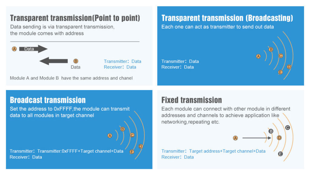
Transmission type
Transmission mode: The first three bytes of each user’s data frame can be used as high/low address and channel in fixed transmission mode. The module changes its address and channel when transmitted. And it will revert to the original setting after completing the process.
| Fixed transmission enabling bit | Constant value |
|---|---|
| Fixed transmission mode | FT_FIXED_TRANSMISSION |
| Transparent transmission mode (default) | FT_TRANSPARENT_TRANSMISSION |
FEC
FEC: after turning off FEC, the actual data transmission rate increases while anti-interference ability decreases. Also, the transmission distance is relatively short, and both communication parties must stay on the same page about turn-on or turn-off FEC.
| 2 | FEC switch | Constant value |
|---|---|---|
| 0 | Turn off FEC | FEC_0_OFF |
| 1 | Turn on FEC (default) | FEC_1_ON |
IO drive
IO drive mode: this bit is used for the module internal pull-up resistor. It also increases the level’s adaptability in case of an open drain. But in some cases, it may need an external pull-up resistor.
| 6 | IO drive mode ( default 1) | Constant value |
|---|---|---|
| 1 | TXD and AUX push-pull outputs, RXD pull-up inputs | IO_D_MODE_PUSH_PULLS_PULL_UPS |
| 0 | TXD、AUX open-collector outputs, RXD open-collector inputs | IO_D_MODE_OPEN_COLLECTOR |
WOR cycle
If WOR is transmitting: after the WOR receiver receives the wireless data and outputs it through the serial port, it will wait for 1000ms before entering the WOR again. Users can input the serial port data and return it via wireless during this period. Each serial byte will be refreshed for 1000ms. Users must transmit the first byte within 1000ms.
- Period T = (1 + WOR) * 500ms, maximum 4000ms, minimum 500ms
- The longer the WOR monitoring interval period, the lower the average power consumption, but the greater the data delay
- Both the transmitter and the receiver must be the same (very important).
| Wireless wake-up time | Constant value |
|---|---|
| 500ms | WAKE_UP_500 |
| 1000ms | WAKE_UP_1000 |
| 1500ms | WAKE_UP_1500 |
| 2000ms (default) | WAKE_UP_2000 |
| 2500ms | WAKE_UP_2500 |
| 3000ms | WAKE_UP_3000 |
| 3500ms | WAKE_UP_3500 |
| 4000ms | WAKE_UP_4000 |
Transmission power
You can change this set of constants by applying a define like so:
#define E70_22 // default value without set
Applicable for E70 with 22dBm as max power.
Low power transmission is not recommended due to its low power supply efficiency.
| Transmission power (approximation) | Constant value |
|---|---|
| 22dBm (default) | POWER_22 |
| 17dBm | POWER_17 |
| 13dBm | POWER_13 |
| 10dBm | POWER_10 |
Applicable for E70 with 30dBm as max power.
Low power transmission is not recommended due to its low power supply efficiency.
#define E70_30
| Transmission power (approximation) | Constant value |
|---|---|
| 30dBm (default) | POWER_30 |
| 27dBm | POWER_27 |
| 24dBm | POWER_24 |
| 21dBm | POWER_21 |
You can configure Channel frequency also with this define:
// One of
#define FREQUENCY_433
#define FREQUENCY_868
#define FREQUENCY_900
#define FREQUENCY_915
Check buffer
First, we must introduce a simple but practical method to check if something is in the receiving buffer.
int available();
It’s simple to return how many bytes you have in the current stream.
Send receive messages
Normal transmission mode
Normal/Transparent transmission mode sends messages to all devices with the same address and channel.
There are a lot of methods to send/receive messages, and we are going to explain in detail:
        ResponseStatus sendMessage(const String message);
        ResponseContainer receiveMessage();
The first method is sendMessage, which sends a String to a device in Normal mode.
	ResponseStatus rs = e70ttl.sendMessage("Prova");
	Serial.println(rs.getResponseDescription());
The other device does on the loop.
       if (e70ttl.available()  > 1){
		ResponseContainer rs = e70ttl.receiveMessage();
		String message = rs.data; // First ever get the data
		Serial.println(rs.status.getResponseDescription());
		Serial.println(message);
	}
Pay attention if you receive multiple messages in the buffer and don’t want to read them all at one time. You must use ResponseContainer rs = e70ttl.receiveMessageUntil(); with a delimiter put on the end of sending a message.
Manage structure
If you want to send a complex structure, you can use this method
        ResponseStatus sendMessage(const void *message, const uint8_t size);
        ResponseStructContainer receiveMessage(const uint8_t size);
It’s used to send structure, for example:
	struct Messaggione {
		char type[5];
		char message[8];
		bool mitico;
	};
        struct Messaggione messaggione = {"TEMP", "Peple", true};
        ResponseStatus rs = e70ttl.sendMessage(&messaggione, sizeof(Messaggione));
	Serial.println(rs.getResponseDescription());
and the other side, you can receive the message so
		ResponseStructContainer rsc = e70ttl.receiveMessage(sizeof(Messaggione));
		struct Messaggione messaggione = *(Messaggione*) rsc.data;
		Serial.println(messaggione.message);
		Serial.println(messaggione.mitico);
        rsc.close();
Read partial structure
If you want to read the first part of the message to manage more types of structure, you can use this method.
ResponseContainer receiveInitialMessage(const uint8_t size);
I create It to receive a string with type or other to identify the structure to load.
		struct Messaggione { // Partial structure without type
			char message[8];
			bool mitico;
		};

		char type[5]; // first part of structure
		ResponseContainer rs = e70ttl.receiveInitialMessage(sizeof(type));
                // Put string in a char array (not needed)
		memcpy ( type, rs.data.c_str(), sizeof(type) );

		Serial.println("READ TYPE: ");
		Serial.println(rs.status.getResponseDescription());
		Serial.println(type);

                // Read the rest of structure
		ResponseStructContainer rsc = e70ttl.receiveMessage(sizeof(Messaggione));
		struct Messaggione messaggione = *(Messaggione*) rsc.data;
        rsc.close();
Fixed mode instead of normal mode
Similarly, I create a set of methods to use with the fixed transmission.
Fixed transmission
You need to change only the sending method because the destination device doesn’t receive the preamble with Address and Channel when setting the fixed mode.
So for the String message, you have
        ResponseStatus sendFixedMessage(byte ADDH, byte ADDL, byte CHAN, const String message);
        ResponseStatus sendBroadcastFixedMessage(byte CHAN, const String message);
and for the structure, you have
        ResponseStatus sendFixedMessage(byte ADDH, byte ADDL, byte CHAN, const void *message, const uint8_t size);
        ResponseStatus sendBroadcastFixedMessage(byte CHAN, const void *message, const uint8_t size );
Here is a simple example
	ResponseStatus rs = e70ttl.sendFixedMessage(0, 0, 0x17, &messaggione, sizeof(Messaggione));
//	ResponseStatus rs = e70ttl.sendFixedMessage(0, 0, 0x17, "Ciao");
Fixed transmission has more scenarios
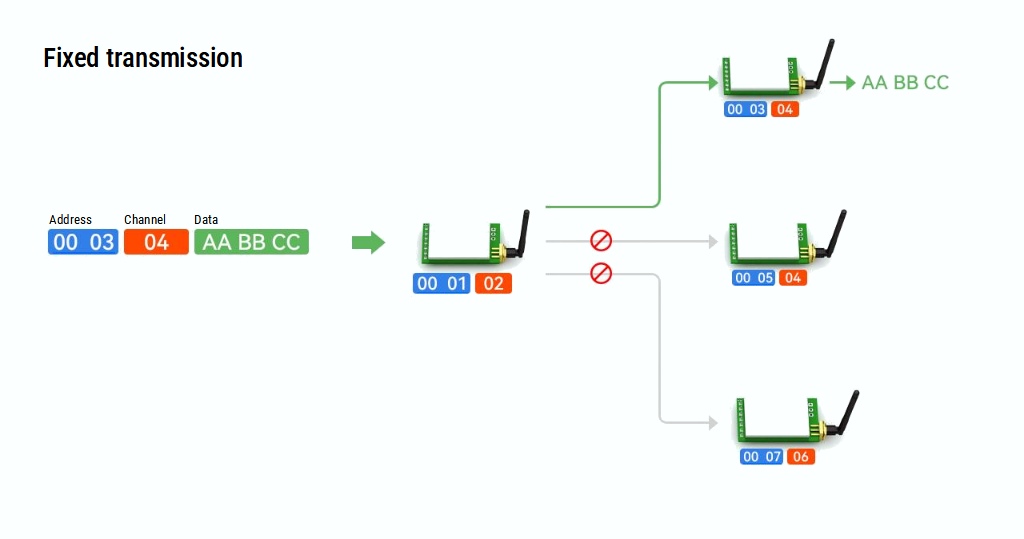
If you send it to a specific device (second scenario Fixed transmission), you must add ADDL, ADDH, and CHAN to identify It directly.
ResponseStatus rs = e70ttl.sendFixedMessage(2, 2, 0x17, "Message to a device");
If you want to send a message to all devices in a specified Channel, you can use this method.
ResponseStatus rs = e70ttl.sendBroadcastFixedMessage(0x17, "Message to a devices of a channel");
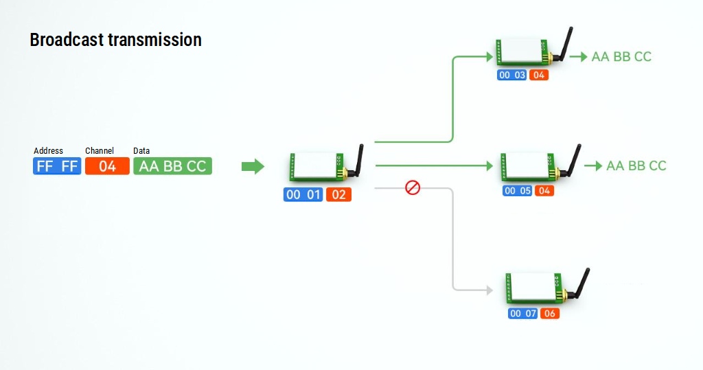
If you wish to receive all broadcast messages in the network, you must set your ADDH and ADDL with BROADCAST_ADDRESS.
        ResponseStructContainer c;
	c = e70ttl.getConfiguration();
	// It's important get configuration pointer before all other operation
	Configuration configuration = *(Configuration*) c.data;
	Serial.println(c.status.getResponseDescription());
	Serial.println(c.status.code);

	printParameters(configuration);
	configuration.ADDL = BROADCAST_ADDRESS;
	configuration.ADDH = BROADCAST_ADDRESS;

	// Set configuration changed and set to not hold the configuration
	ResponseStatus rs = e70ttl.setConfiguration(configuration, WRITE_CFG_PWR_DWN_LOSE);
	Serial.println(rs.getResponseDescription());
	Serial.println(rs.code);
	printParameters(configuration);
        c.close();
Continuous mode
E70 offers the continuous mode by setting the same ADDH, ADDL, and CHAN. You can stream a lot of data or continuous data.
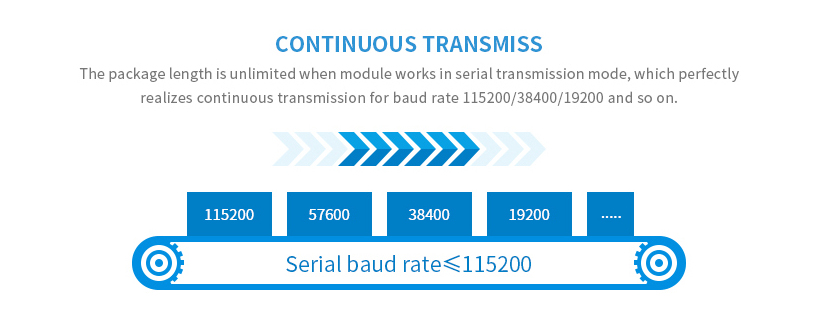
Continuous Mode
- Operation: In continuous mode, the EByte E70 module sends or receives data in a continuous stream. This means that once the transmission starts, it will keep sending data until stopped. It’s similar to a traditional radio broadcast.
- Usage: This mode is useful for applications where a constant flow of information is needed, without interruptions. It’s ideal for real-time data transmission, like streaming audio or telemetry.
- Advantages:
- Real-time data transmission: Useful for applications requiring live updates.
- No interruption: Continuous data flow without the need for packet reassembly or handling.
- Challenges:
- Power consumption: Typically, continuous mode consumes more power due to the constant transmission.
- Bandwidth usage: It can use more bandwidth, which might not be ideal in crowded RF environments.
Sub-Packet Mode
- Operation: In sub-packet mode, data is divided into smaller packets before transmission. Each packet is sent separately and then reassembled at the receiver’s end.
- Usage: This mode is ideal for applications that don’t require real-time transmission and can tolerate some delay, such as sending sensor data at intervals.
- Advantages:
- Energy efficiency: More energy-efficient as the module can go into a low-power state between transmissions.
- Error handling: Easier to implement error checking and correction, as it’s done on a per-packet basis.
- Adaptive data rates: Can adjust the data rate for each packet depending on network conditions.
- Challenges:
- Latency: There is a delay in data reassembly, which might not be suitable for real-time applications.
- Complexity: Requires more complex logic for packet handling and reassembly.
Key Differences
- Data Transmission Method: Continuous mode transmits data in a constant stream, while sub-packet mode breaks data into smaller packets.
- Power Consumption: Continuous mode generally consumes more power due to the constant transmission.
- Real-time Capability: Continuous mode is better for real-time data needs, whereas sub-packet mode is suitable for delayed or periodic data transmission.
- Error Handling and Flexibility: Sub-packet mode provides more flexibility in error handling and adjusting to network conditions.
When you use continuous transmission mode, the module sends a continuous stream of data. To target this data to a specific address, you would typically configure the sender and receiver with matching addresses. This means that both the transmitting and receiving modules should be set up to recognize and use these specified addresses.
Simple stream
To send a simple stream (without any preamble) you can use
ResponseStatus RF_E70::streamMessage(Stream *streamLocal)
A possible implementation can be the stream of a file.
			File inputFile = SPIFFS.open(input);

			if (!inputFile) {
			    Serial.println("There was an error opening the file for reading");
			} else  {
				ResponseStatus rs = e70ttl.streamMessage(&inputFile);
				// Check If there is some problem of succesfully send
				Serial.println(rs.getResponseDescription());
			}
That takes a stream as a parameter. To receive It, you can wait for the data.
    if (e70ttl.available()>0) {
    	Serial.println("Start!");

  	  // open file in write
    	File output = SPIFFS.open("/tmp.png", FTP_FILE_WRITE_CREATE);

    	while (e70ttl.available()>0) {
			while (e70ttl.available()>0) {
				if (output.write(e70ttl.read())==0) {Serial.println("ERROR WRITE!"); };
			}
	    	delay(10);
    	}

    	output.close();

    	Serial.println("Complete!");
    }
As you can see, you can use read, which is a classical stream.read().
Stream with preamble
Not all situations can be a continuous stream; sometimes, we need to send data as a byte array; in this situation, you need a preamble with the file information, and you can use the command.
ResponseStatus RF_E70::streamStructMessage(const void *message, const uint8_t size, Stream *streamLocal)
You can identify the first part of the send method It’s the same as the send struct described before; the last parameter is the stream to send.
To receive all, you must first call the command to get the structure (preamble)
ResponseStructContainer RF_E70::receiveStreamMessage(const uint8_t size)
Then, we get the stream as already described.
Thanks
- EByte RF E70 433/868/900 T14S2: pinout, datasheet and specs (1.5Km)
- EByte RF E70 Module Adapter: PCB, 3D Printed, Breadboard-Friendly Solution and configuration
- Connecting the EByte E70 to ESP32 c3/s3 devices and a simple sketch example
- Connecting the EByte E70 to Arduino SAMD (Nano 33, MKR…) devices and a simple sketch example
- Connecting the EByte E70 to STM32 (black/blue pill) devices and a simple sketch example
- Connecting the EByte E70 to Raspberry Pi Pico (rp2040) devices and a simple sketch example
- Exploring the Capabilities of the EByte RF E70 Module (esp32, STM32, Arduino, Raspberry Pi Pico)
- EByte RF E70 CC1310: exploring library (esp32, esp8266, STM32, Arduino, Raspberry Pi Pico)
- Configuration of EByte RF E70 Module (esp32, STM32, Arduino, Raspberry Pi Pico)