BNO055 for esp32, esp8266, and Arduino: wiring and advanced Bosch library – 2
This is the second article on bno055. If you need basic management, you can refer to the previous article, “BNO055 accelerometer, gyroscope, magnetometer with basic Adafruit library“, but if you need advanced management (and more complex) with interrupt, you must read this article also.
The BNO055 is a System in Package (SiP), integrating a triaxial 14-bit accelerometer, a triaxial 16-bit gyroscope with a range of ±2000 degrees per second, a triaxial geomagnetic sensor, and a 32-bit cortex M0+ microcontroller running Bosch Sensortec sensor fusion software, in a single package.
The BNO055 can output the following sensor data:
- Absolute Orientation (Euler Vector, 100Hz) Three-axis orientation data based on a 360° sphere
- Absolute Orientation (Quaternion, 100Hz) Four-point quaternion output for more accurate data manipulation
- Angular Velocity Vector (100Hz) Three axis of ‘rotation speed’ in rad/s
- Acceleration Vector (100Hz) Three axis of acceleration (gravity + linear motion) in m/s^2
- Magnetic Field Strength Vector (20Hz) Three axis of magnetic field sensing in micro Tesla (uT)
- Linear Acceleration Vector (100Hz) Three axis of linear acceleration data (acceleration minus gravity) in m/s^2
- Gravity Vector (100Hz) Three axis of gravitational acceleration (minus any movement) in m/s^2
- Temperature (1Hz) Ambient temperature in degrees celsius
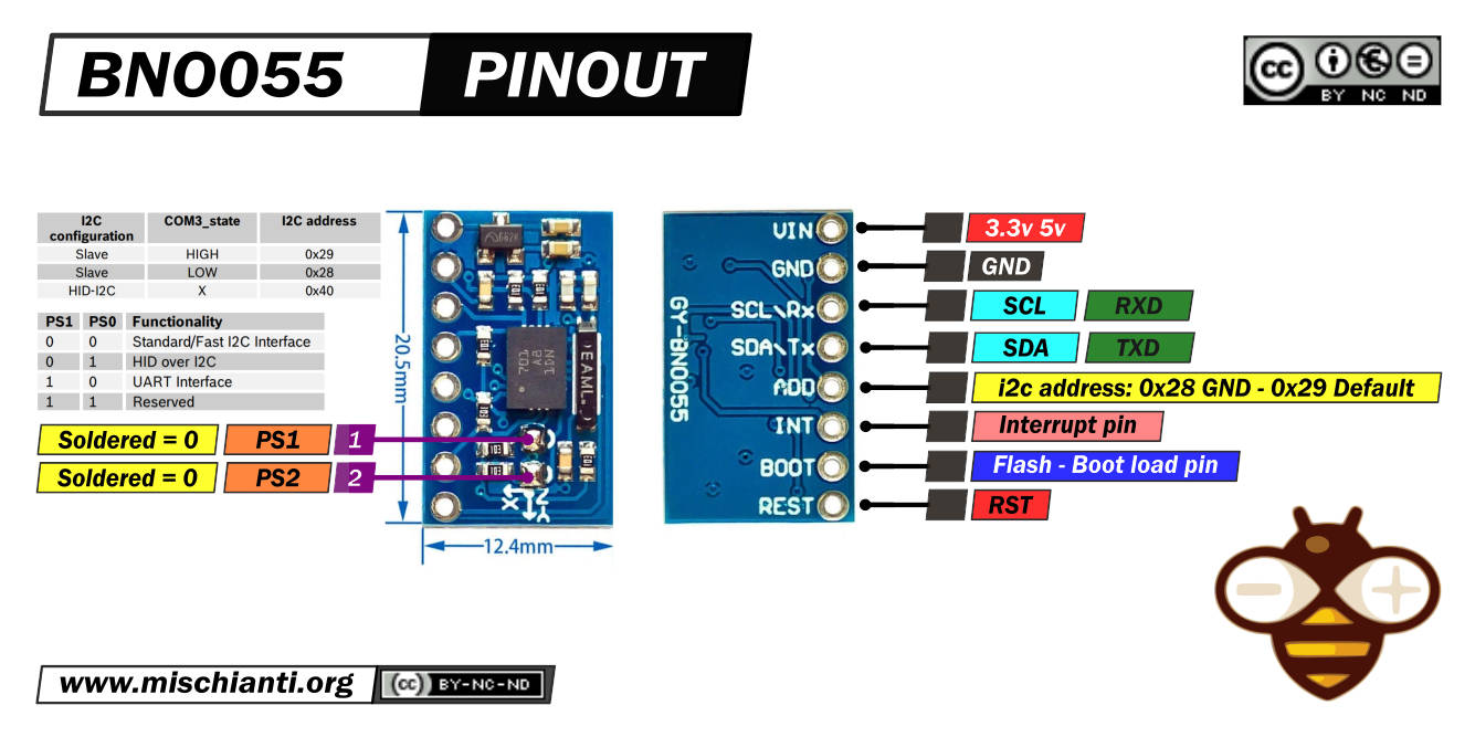
BNO055 pinouts
Exists a lot of module versions of this sensor, I choose the smallest and cheap.
Here the module Aliexpress
All these modules had the same features, but to enable them, you must do different operations.
This is the clone I use:
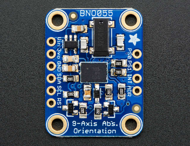
And here is the Adafruit one:
The sensor supports a 3.3v logic level, but the module can be powered by 5v.
You can communicate via i2c (default option) and via UART, to activate the last modality you must desolder PS1.
| PS1 | PS0 | Functionality |
|---|---|---|
| 0 | 0 | Standard/Fast I2C Interface |
| 0 | 1 | HID over I2C |
| 1 | 0 | UART Interface |
| 1 | 1 | Reserved |
In standard i2c mode, you can select two addresses. By default, in this module, the address 0x29 is active. If you put to GND the ADD pin, the address becomes 0x28.
| i2c configuration | ADD | I2C address |
|---|---|---|
| Slave | HIGH | 0x29 |
| Slave | LOW (default) | 0x28 |
| HID-I2C | 0x40 |
INT is configured as an interrupt pin for signaling an interrupt to the host. The interrupt trigger is configured as a raising edge and is latched onto the INT pin. Once an interrupt occurs, the INT pin is set to high and will remain high until it is reset by the host.
Basic connections
For basic i2c usage, you must only connect VCC, GND, SDA, and SCL.
Wiring Arduino UNO
The Adafruit version of the sensor is well documented, and It fully supports the 5v logic level.
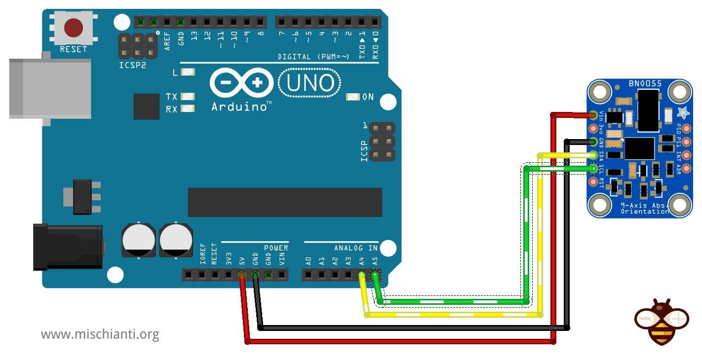
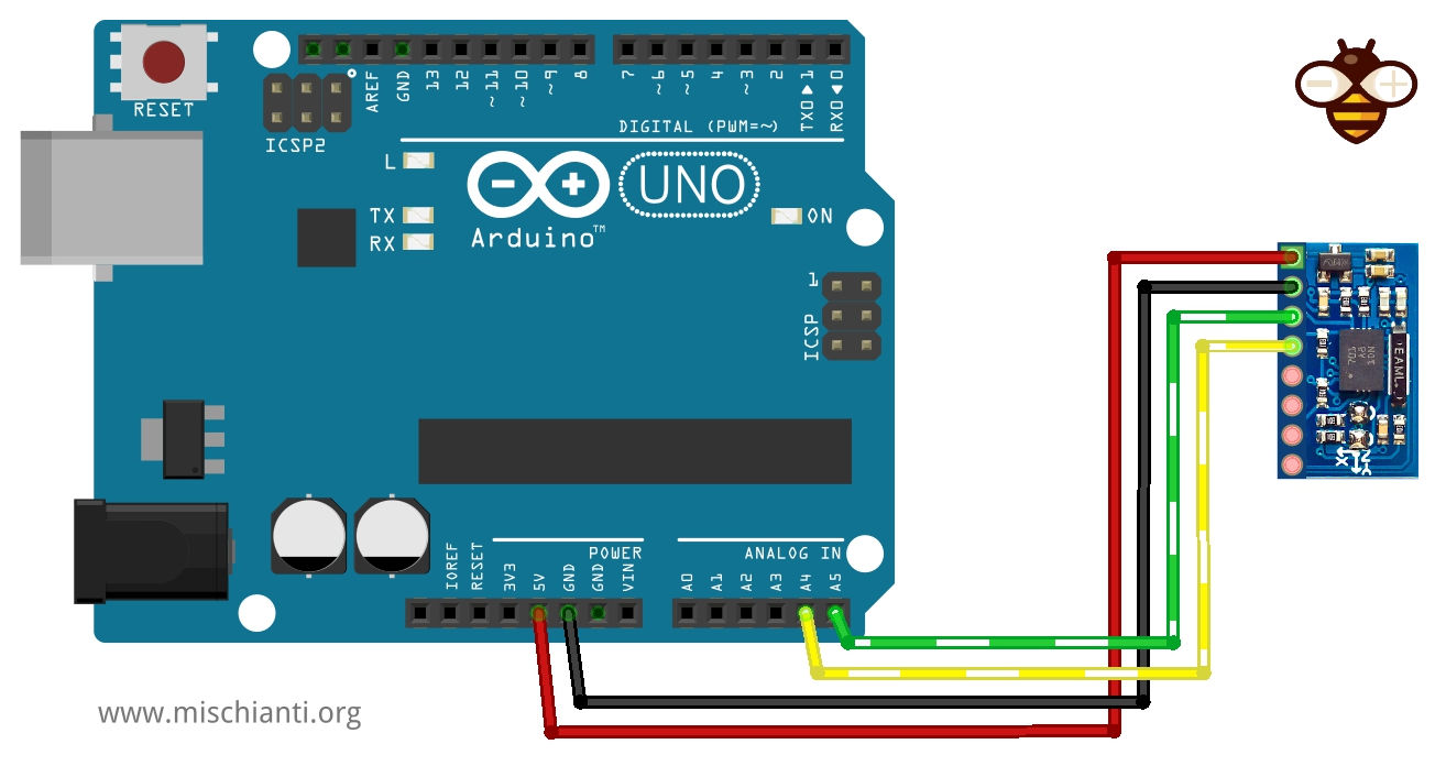
The clone version was not clear if It fully supports a 5v logic level, but it surely supports a 5v power supply. I try to use Arduino UNO, and It works correctly without LLC.
Here the Arduino boards Arduino UNO - Arduino MEGA 2560 R3 - Arduino Nano - Arduino Pro Mini
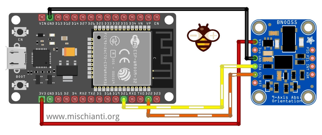
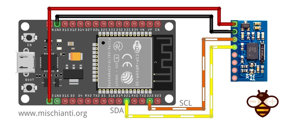
Wiring esp32
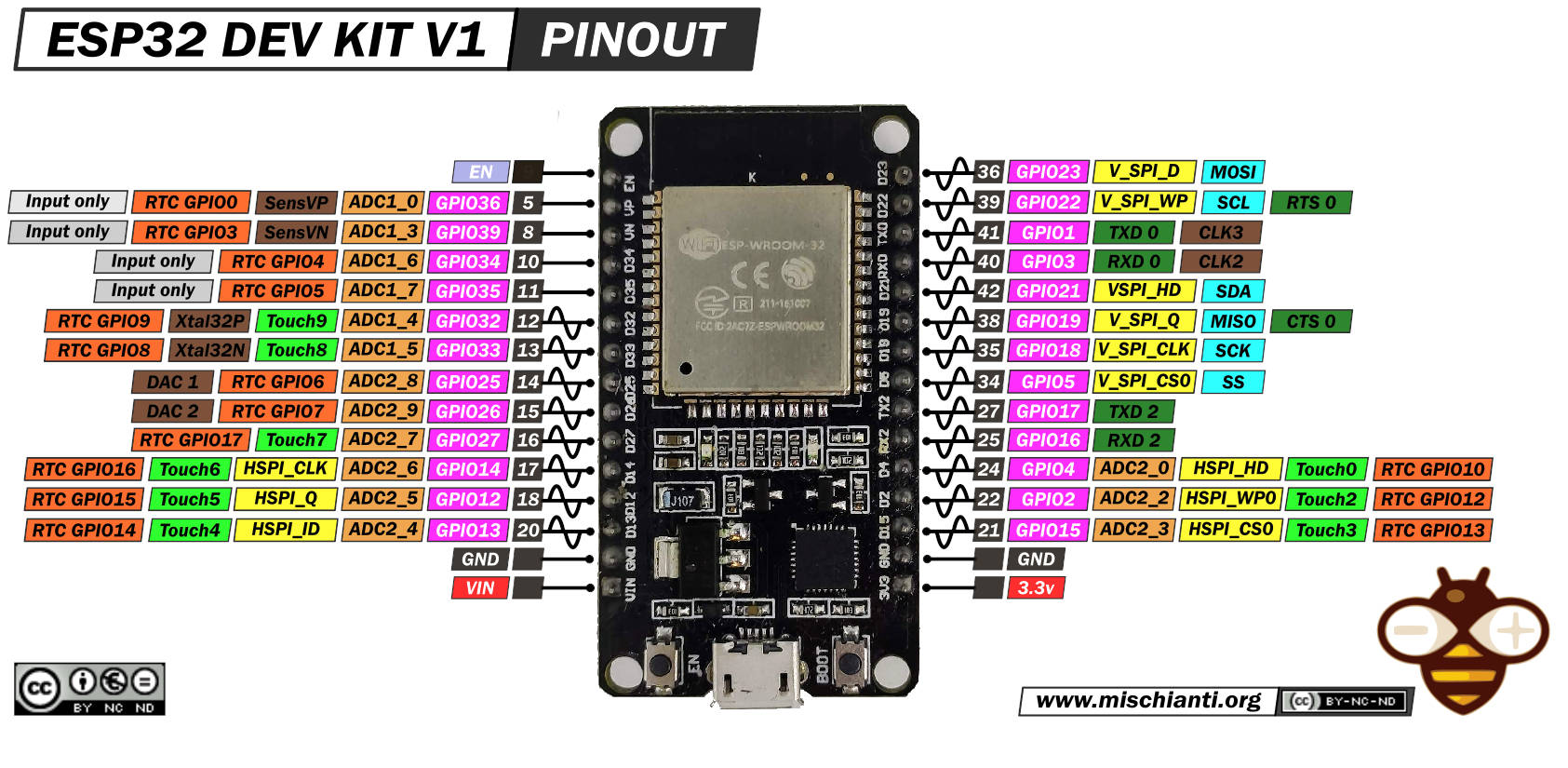
The esp32 worked at 3.3v, so wiring was easier.
And here is the clone.
Here my selection of esp32 ESP32 Dev Kit v1 - TTGO T-Display 1.14 ESP32 - NodeMCU V3 V2 ESP8266 Lolin32 - NodeMCU ESP-32S - WeMos Lolin32 - WeMos Lolin32 mini - ESP32-CAM programmer - ESP32-CAM bundle - ESP32-WROOM-32 - ESP32-S
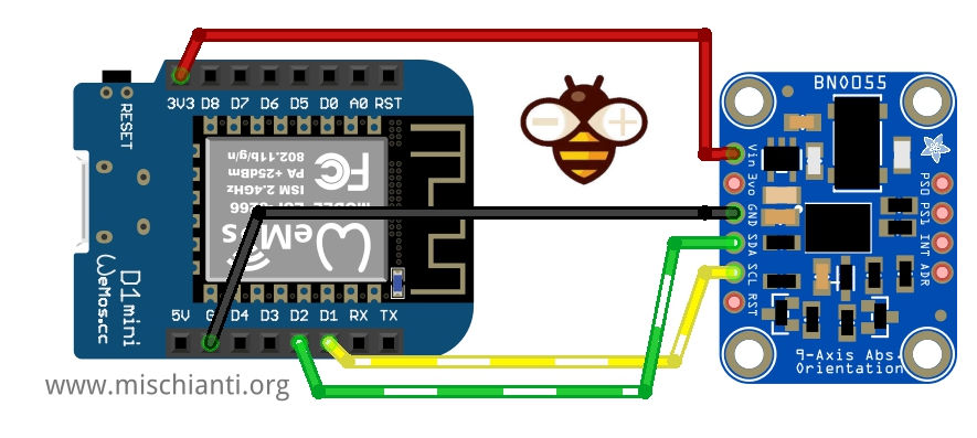
Wiring esp8266
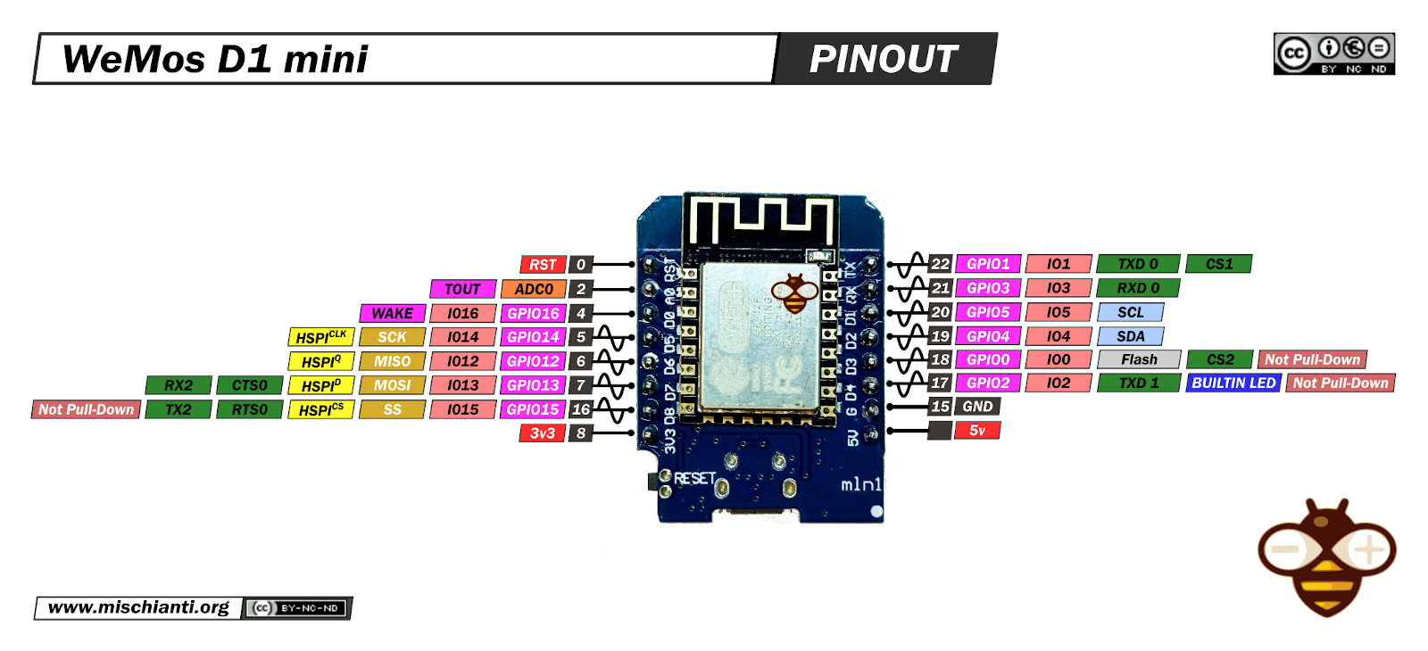
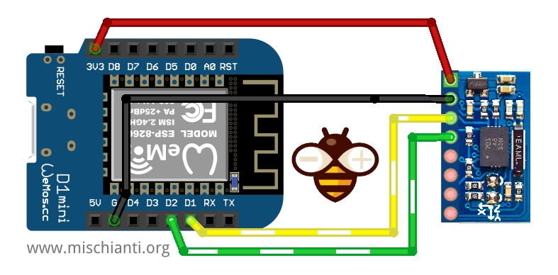
esp8266 like esp32 work at 3.3v, so the wiring is linear.
And now the clone.
Here my selection of esp8266 boards WeMos D1 mini - NodeMCU V2 V2.1 V3 - esp01 - esp01 programmer
Bosch complete library
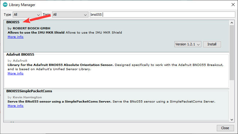
Bosh offers a completed but undocumented and not structured library.
You can download the library from GitHub here. Or you can directly download it from the Arduino IDE libraries manager.
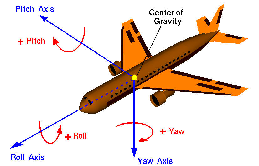
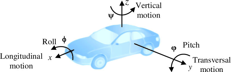
Yaw, roll, and pitch sketch example
When we need to control robotics, aero, or machine, the better solution is to use Yaw, roll, and pitch. I added some figures to understand where these values are positioned.
The bosh sensor can give elaborated data, one example is the Euler_Streaming on the BNO055 library.
/*
 ***************************************************************************

    Euler_Streaming.pde - part of sample SW for using BNO055 with Arduino

   (C) All rights reserved by ROBERT BOSCH GMBH

   Copyright (C) 2014 Bosch Sensortec GmbH

 	This program is free software: you can redistribute it and/or modify
    it under the terms of the GNU General Public License as published by
    the Free Software Foundation, either version 3 of the License, or
   (at your option) any later version.

    This program is distributed in the hope that it will be useful,
    but WITHOUT ANY WARRANTY; without even the implied warranty of
    MERCHANTABILITY or FITNESS FOR A PARTICULAR PURPOSE.  See the
    GNU General Public License for more details.

    You should have received a copy of the GNU General Public License
    along with this program.  If not, see <http://www.gnu.org/licenses/>.

 **************************************************************************/
/*	Date: 2014/01/07
 	 Revision: 1.2

*/

#include "BNO055_support.h"		//Contains the bridge code between the API and Arduino
#include <Wire.h>

//The device address is set to BNO055_I2C_ADDR2 in this example. You can change this in the BNO055.h file in the code segment shown below.
// /* bno055 I2C Address */
// #define BNO055_I2C_ADDR1                0x28
// #define BNO055_I2C_ADDR2                0x29
// #define BNO055_I2C_ADDR                 BNO055_I2C_ADDR2

//Pin assignments as tested on the Arduino Due.
//Vdd,Vddio : 3.3V
//GND : GND
//SDA/SCL : SDA/SCL
//PSO/PS1 : GND/GND (I2C mode)

//This structure contains the details of the BNO055 device that is connected. (Updated after initialization)
struct bno055_t myBNO;
struct bno055_euler myEulerData; //Structure to hold the Euler data

unsigned long lastTime = 0;

void setup() //This code is executed once
{
  //Initialize I2C communication
  Wire.begin();

  //Initialization of the BNO055
  BNO_Init(&myBNO); //Assigning the structure to hold information about the device

  //Configuration to NDoF mode
  bno055_set_operation_mode(OPERATION_MODE_NDOF);

  delay(1);

  //Initialize the Serial Port to view information on the Serial Monitor
  Serial.begin(115200);
}

void loop() //This code is looped forever
{
  if ((millis() - lastTime) >= 100) //To stream at 10Hz without using additional timers
  {
    lastTime = millis();

    bno055_read_euler_hrp(&myEulerData);			//Update Euler data into the structure

    Serial.print("Time Stamp: ");				//To read out the Time Stamp
    Serial.println(lastTime);

    Serial.print("Heading(Yaw): ");				//To read out the Heading (Yaw)
    Serial.println(float(myEulerData.h) / 16.00);		//Convert to degrees

    Serial.print("Roll: ");					//To read out the Roll
    Serial.println(float(myEulerData.r) / 16.00);		//Convert to degrees

    Serial.print("Pitch: ");				//To read out the Pitch
    Serial.println(float(myEulerData.p) / 16.00);		//Convert to degrees

    Serial.println();					//Extra line to differentiate between packets
  }
}
And the result in serial output is:
Time Stamp: 6500
Heading(Yaw): 182.50
Roll: -3.44
Pitch: -26.00

Time Stamp: 6600
Heading(Yaw): 187.69
Roll: -16.37
Pitch: -18.69

Time Stamp: 6700
Heading(Yaw): 193.50
Roll: -27.75
Pitch: -8.25

Time Stamp: 6800
Heading(Yaw): 197.44
Roll: -34.81
Pitch: 1.19

Time Stamp: 6900
Heading(Yaw): 199.87
Roll: -37.25
Pitch: 9.00

Time Stamp: 7000
Heading(Yaw): 201.25
Roll: -36.88
Pitch: 16.25

Time Stamp: 7100
Heading(Yaw): 199.94
Roll: -30.75
Pitch: 21.94

Time Stamp: 7200
Heading(Yaw): 198.25
Roll: -20.62
Pitch: 27.50

Time Stamp: 7300
Heading(Yaw): 196.50
Roll: -12.44
Pitch: 30.31

Time Stamp: 7400
Heading(Yaw): 196.19
Roll: -4.06
Pitch: 31.44

Time Stamp: 7500
Heading(Yaw): 194.31
Roll: 4.50
Pitch: 31.31

Time Stamp: 7600
Heading(Yaw): 190.56
Roll: 12.75
Pitch: 28.00

Time Stamp: 7700
Heading(Yaw): 186.87
Roll: 22.94
Pitch: 23.12

Time Stamp: 7800
Heading(Yaw): 184.62
Roll: 29.81
Pitch: 19.37

Time Stamp: 7900
Heading(Yaw): 182.75
Roll: 35.19
Pitch: 15.94

Time Stamp: 8000
Heading(Yaw): 181.12
Roll: 42.63
Pitch: 11.63

Time Stamp: 8100
Heading(Yaw): 180.37
Roll: 47.56
Pitch: 9.13

Time Stamp: 8200
Heading(Yaw): 181.69
Roll: 53.44
Pitch: 4.12

Time Stamp: 8300
Heading(Yaw): 184.31
Roll: 57.81
Pitch: -0.94

Time Stamp: 8400
Heading(Yaw): 183.44
Roll: 60.81
Pitch: -3.62
These values were the basic elements for all machines, such as cars or boats.
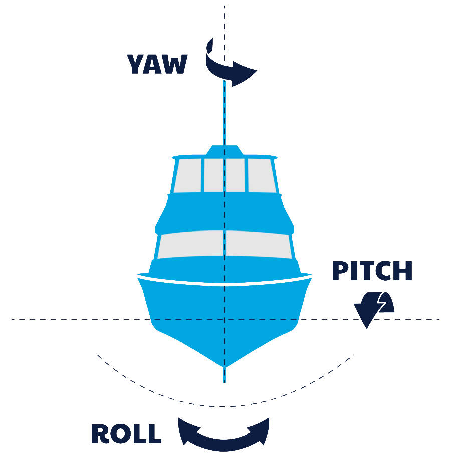
And can be managed with 10Hz frequencies. I checked that the noise was managed very well.
Move 3d bunny with WebGL and absolute position.
Here I write a simple sketch like Adafruit one (check the previous BNO055 article) that reads the serial data and converts it to a 3D rotation to do that in a simple way using Web Serial API for Chrome browser.
So first, you need Chrome.
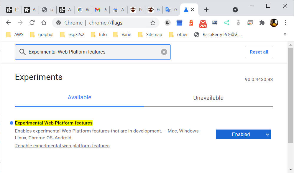
Then you must enable WebSerial API, and do that, you must put in the browser input URL chrome://flags then search (with Ctrl+f) Experimental Web Platform features and enable It.
Then load the example.
/**
 * Simple example with bosch library for bno055 to work with
 * Adafruit webGL example with euler angles
 * https://adafruit.github.io/Adafruit_WebSerial_3DModelViewer/
 *
 * by Renzo Mischianti <www.mischianti.org>
 *
 * https://mischianti.org/
 */

#include "BNO055_support.h"		//Contains the bridge code between the API and Arduino
#include <Wire.h>

//The device address is set to BNO055_I2C_ADDR2 in this example. You can change this in the BNO055.h file in the code segment shown below.
// /* bno055 I2C Address */
// #define BNO055_I2C_ADDR1                0x28
// #define BNO055_I2C_ADDR2                0x29
// #define BNO055_I2C_ADDR                 BNO055_I2C_ADDR2

//Pin assignments as tested on the Arduino Due.
//Vdd,Vddio : 3.3V
//GND : GND
//SDA/SCL : SDA/SCL
//PSO/PS1 : GND/GND (I2C mode)

//This structure contains the details of the BNO055 device that is connected. (Updated after initialization)
struct bno055_t myBNO;
struct bno055_euler myEulerData; //Structure to hold the Euler data

unsigned char accelCalibStatus = 0;		//Variable to hold the calibration status of the Accelerometer
unsigned char magCalibStatus = 0;		//Variable to hold the calibration status of the Magnetometer
unsigned char gyroCalibStatus = 0;		//Variable to hold the calibration status of the Gyroscope
unsigned char sysCalibStatus = 0;		//Variable to hold the calibration status of the System (BNO055's MCU)

unsigned long lastTime = 0;

/* Set the delay between fresh samples */
#define BNO055_SAMPLERATE_DELAY_MS (100)

void setup() //This code is executed once
{
  //Initialize I2C communication
  Wire.begin();

  //Initialization of the BNO055
  BNO_Init(&myBNO); //Assigning the structure to hold information about the device

  //Configuration to NDoF mode
  bno055_set_operation_mode(OPERATION_MODE_NDOF);

  delay(1);

  //Initialize the Serial Port to view information on the Serial Monitor
  Serial.begin(115200);
}

void loop() //This code is looped forever
{
  if ((millis() - lastTime) >= BNO055_SAMPLERATE_DELAY_MS) //To stream at 10Hz without using additional timers
  {
    lastTime = millis();

    bno055_read_euler_hrp(&myEulerData);			//Update Euler data into the structure

    /* The WebSerial 3D Model Viewer expects data as heading, pitch, roll */
    Serial.print(F("Orientation: "));
    Serial.print(360-(float(myEulerData.h) / 16.00));
    Serial.print(F(", "));
    Serial.print(360-(float(myEulerData.p) / 16.00));
    Serial.print(F(", "));
    Serial.print(360-(float(myEulerData.r) / 16.00));
    Serial.println(F(""));

	bno055_get_accelcalib_status(&accelCalibStatus);
	bno055_get_gyrocalib_status(&gyroCalibStatus);
	bno055_get_syscalib_status(&sysCalibStatus);
	bno055_get_magcalib_status(&magCalibStatus);

	Serial.print(F("Calibration: "));
	Serial.print(sysCalibStatus, DEC);
	Serial.print(F(", "));
	Serial.print(gyroCalibStatus, DEC);
	Serial.print(F(", "));
	Serial.print(accelCalibStatus, DEC);
	Serial.print(F(", "));
	Serial.print(magCalibStatus, DEC);
	Serial.println(F(""));


  }
}
Now open in the browser this URL:
https://adafruit.github.io/Adafruit_WebSerial_3DModelViewer/
Select 115200 baud, click connect and select the correct device serial port.
The result is that you can change the orientation of the bunny with the movement of bno055.
Thanks
- BNO055 accelerometer, gyroscope, magnetometer with basic Adafruit library
- BNO055 for esp32, esp8266, and Arduino: wiring and advanced Bosch library
- BNO055 for esp32, esp8266, and Arduino: features, configuration, and axes remap
- BNO055: power modes, accelerometer, and motion interrupt
- BNO055 for esp32, esp8266, and Arduino: enable INT pin and accelerometer High G Interrupt
- BNO055 for esp32, esp8266, and Arduino: Gyroscope High Rate and Any Motion Interrupt