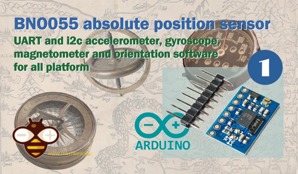
BNO055 accelerometer, gyroscope, magnetometer with basic Adafruit library – 1
The BNO055 is a System in Package (SiP), integrating a triaxial 14-bit accelerometer, a triaxial 16-bit gyroscope with a range of ±2000 degrees per second, a triaxial geomagnetic sensor, and a 32-bit cortex M0+ microcontroller running Bosch Sensortec sensor fusion software, in a single package.
The BNO055 can output the following sensor data:
- Absolute Orientation (Euler Vector, 100Hz) Three axis orientation data based on a 360° sphere
- Absolute Orientation (Quatenrion, 100Hz) Four point quaternion output for more accurate data manipulation
- Angular Velocity Vector (100Hz) Three axis of ‘rotation speed’ in rad/s
- Acceleration Vector (100Hz) Three axis of acceleration (gravity + linear motion) in m/s^2
- Magnetic Field Strength Vector (20Hz) Three axis of magnetic field sensing in micro Tesla (uT)
- Linear Acceleration Vector (100Hz) Three axis of linear acceleration data (acceleration minus gravity) in m/s^2
- Gravity Vector (100Hz) Three axis of gravitational acceleration (minus any movement) in m/s^2
- Temperature (1Hz) Ambient temperature in degrees celsius
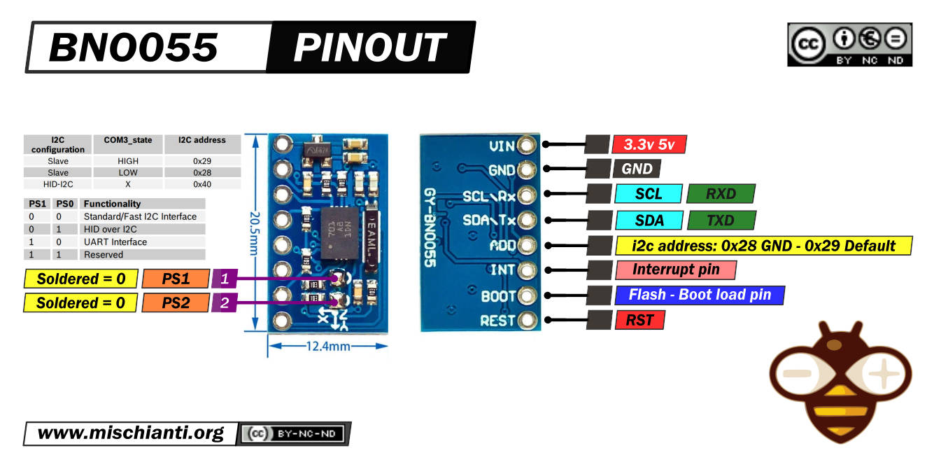
BNO055 pinouts
Exists a lot of module versions of this sensors, i choice the smallest and cheap.
Here the module Aliexpress
All these modules had the same features, but to enable Them you must do different operations.
This is the clone I use:
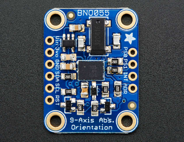
And here is the Adafruit one:
The sensor support a 3.3v logic level, but the module can be powered by 5v.
Can communicate via i2c (default option) and via UART. To activate the last modality you must desolder PS1.
| PS1 | PS0 | Functionality |
|---|---|---|
| 0 | 0 | Standard/Fast I2C Interface |
| 0 | 1 | HID over I2C |
| 1 | 0 | UART Interface |
| 1 | 1 | Reserved |
In standard i2c mode, you can select two address; by default, in this module, the address 0x29 is active; if you put to GND the ADD pin, the address become 0x28.
| i2c configuration | ADD | I2C address |
|---|---|---|
| Slave | HIGH | 0x29 |
| Slave | LOW (default) | 0x28 |
| HID-I2C | 0x40 |
INT is configured as an interrupt pin for signaling an interrupt to the host. The interrupt trigger is configured as a raising edge and is latched onto the INT pin. Once an interrupt occurs, the INT pin is set to high and will remain high until it is reset by the host.
Features
Magnetometer features
A magnetometer is a device that measures magnetic field or magnetic dipole moment. Some magnetometers measure a magnetic field’s direction, strength, or relative change at a particular location.
I write some examples and additional information about magnetometers in this article, “GY-273 QMC5883L clone HMC5883L magnetometer for Arduino, esp8266 and esp32“.
- Flexible functionality
Magnetic field range typical ±1300µT (x-, y-axis);
±2500µT (z-axis)
Magnetic field resolution of ~0.3µT- Operating modes:
- Low power
- Regular
- Enhanced regular
- High Accuracy
- Power modes:
- Normal
- Sleep
- Suspend
- Force
- Operating modes:
Accelerometer features
An accelerometer is a tool that measures proper acceleration. Proper acceleration is the acceleration (the rate of change of velocity) of a body in its own instantaneous rest frame; this is different from coordinate acceleration, which is acceleration in a fixed coordinate system.
I have explained what it is in detail and written various practical application examples in this article, “GY-291 ADXL345 i2c spi accelerometer with interrupt for esp32, esp8266, stm32 and Arduino“.
- Programmable functionality
Acceleration ranges ±2g/±4g/±8g/±16g
Low-pass filter bandwidths 1kHz – <8Hz
Operation modes:- Normal
- Suspend
- Low power
- Standby
- Deep suspend
- On-chip interrupt controller
Motion-triggered interrupt-signal generation for- any-motion (slope) detection
- slow or no motion recognition
- high-g detection
Gyroscope features
A gyroscope is used to measure or maintain orientation and angular velocity. In origin was a spinning wheel or disc in which the axis of rotation (spin axis) is free to assume any orientation by itself.
- Programmable functionality
Ranges switchable from ±125°/s to ±2000°/s
Low-pass filter bandwidths 523Hz – 12Hz
Operation modes:- Normal
- Fast power up
- Deep suspend
- Suspend
- Advanced power save
- On-chip interrupt controller
Motion-triggered interrupt-signal generation for- any-motion (slope) detection
- high rate
Wiring
For basic i2c usage, you must only connect VCC, GND, SDA, and SCL.
Arduino UNO
The Adafruit version of the sensor is well documented and fully supports the 5v logic level.
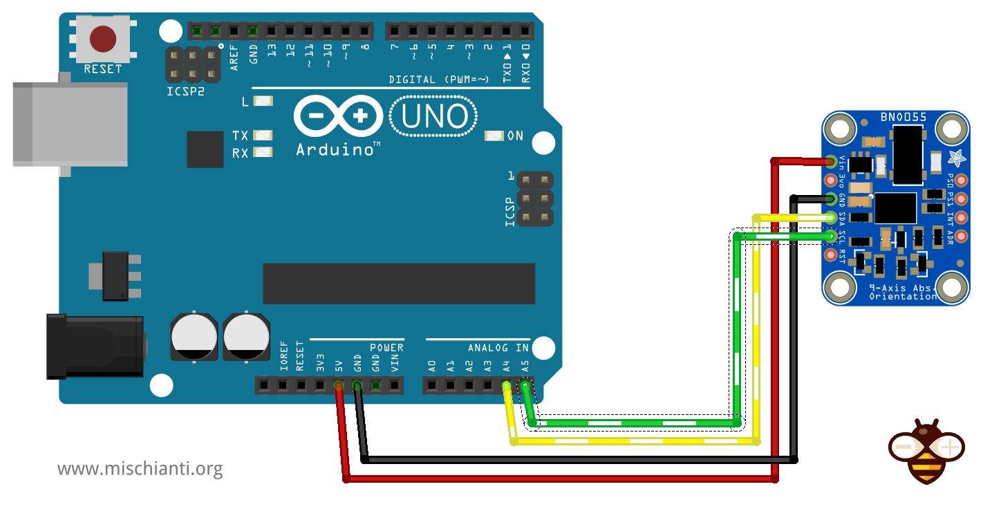
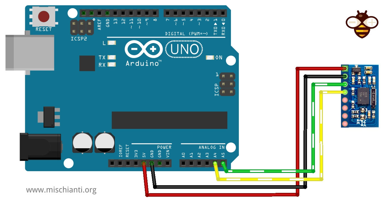
The clone version was not clear if It fully supports the 5v logic level but surely supports the 5v power supply. I try to use Arduino UNO, and It’s works correctly without LLC.
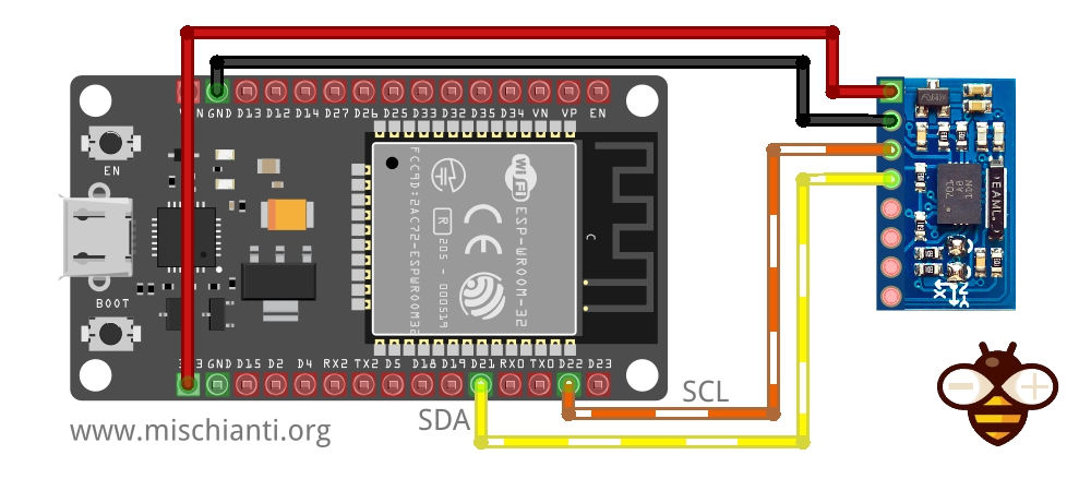
esp32 wiring
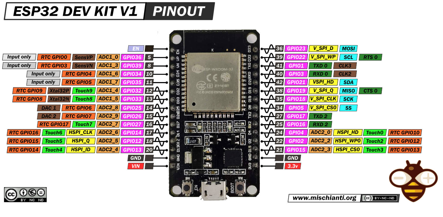
esp32 work at 3.3v, so the wiring was without doubt.
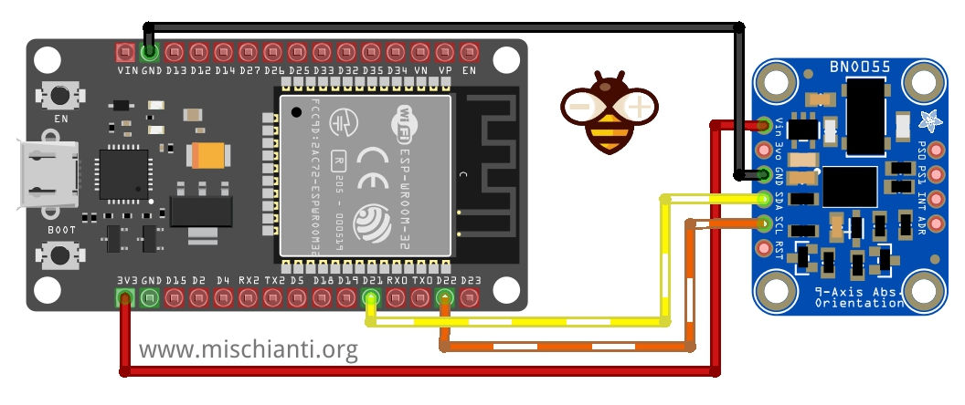
And here is the clone.
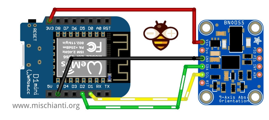
esp8266 wiring
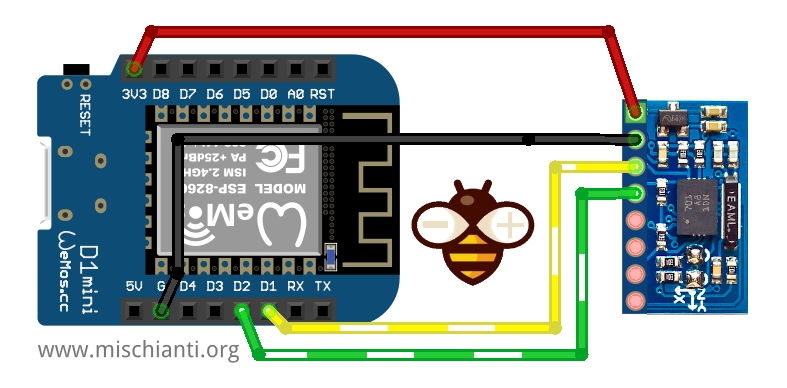
esp8266, like esp32, work at 3.3v, so the wiring is linear.
And now the clone.
Basic library
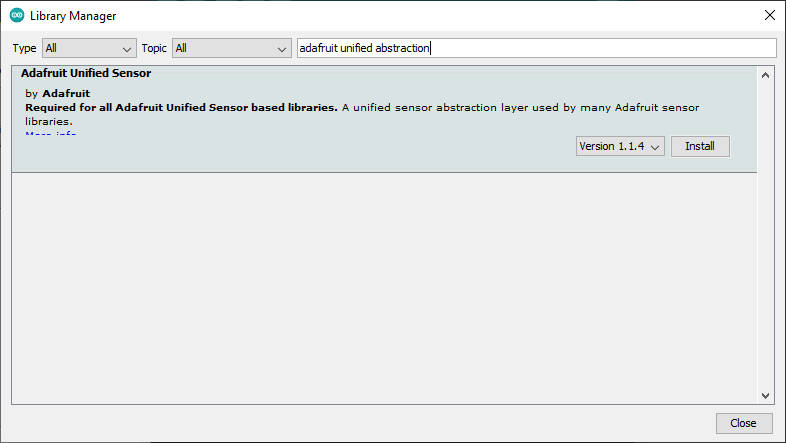
Adafruit (as usual) offers a beautiful and very simple to use library that needs the Adafruit Unified Sensors, but does not support interrupt and can be installed directly from the Arduino library manager.
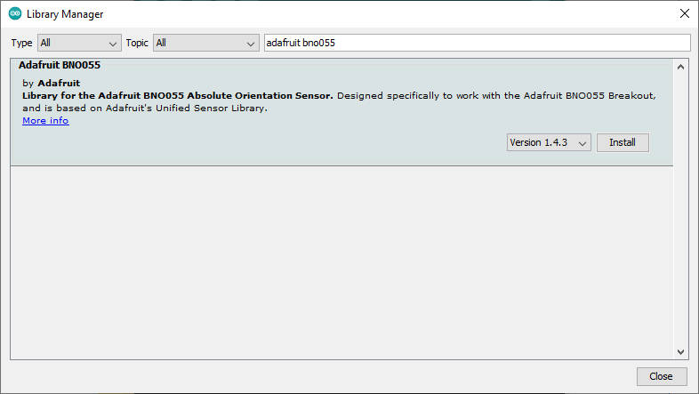
You need to install Adafruit Unified Sensor library as dependencies.
Here the example sketch that show all values that you can grab from the sensor.
#include <Wire.h>
#include <Adafruit_Sensor.h>
#include <Adafruit_BNO055.h>
#include <utility/imumaths.h>

/* This driver uses the Adafruit unified sensor library (Adafruit_Sensor),
   which provides a common 'type' for sensor data and some helper functions.

   To use this driver you will also need to download the Adafruit_Sensor
   library and include it in your libraries folder.

   You should also assign a unique ID to this sensor for use with
   the Adafruit Sensor API so that you can identify this particular
   sensor in any data logs, etc.  To assign a unique ID, simply
   provide an appropriate value in the constructor below (12345
   is used by default in this example).

   Connections
   ===========
   Connect SCL to analog 5
   Connect SDA to analog 4
   Connect VDD to 3.3-5V DC
   Connect GROUND to common ground

   History
   =======
   2015/MAR/03  - First release (KTOWN)
*/

/* Set the delay between fresh samples */
uint16_t BNO055_SAMPLERATE_DELAY_MS = 100;

// Check I2C device address and correct line below (by default address is 0x29 or 0x28)
//                                   id, address
Adafruit_BNO055 bno = Adafruit_BNO055(55, 0x28);

void setup(void)
{
  Serial.begin(115200);
  Serial.println("Orientation Sensor Test"); Serial.println("");

  /* Initialise the sensor */
  if (!bno.begin())
  {
    /* There was a problem detecting the BNO055 ... check your connections */
    Serial.print("Ooops, no BNO055 detected ... Check your wiring or I2C ADDR!");
    while (1);
  }

  delay(1000);
}

void loop(void)
{
  //could add VECTOR_ACCELEROMETER, VECTOR_MAGNETOMETER,VECTOR_GRAVITY...
  sensors_event_t orientationData , angVelocityData , linearAccelData, magnetometerData, accelerometerData, gravityData;
  bno.getEvent(&orientationData, Adafruit_BNO055::VECTOR_EULER);
  bno.getEvent(&angVelocityData, Adafruit_BNO055::VECTOR_GYROSCOPE);
  bno.getEvent(&linearAccelData, Adafruit_BNO055::VECTOR_LINEARACCEL);
  bno.getEvent(&magnetometerData, Adafruit_BNO055::VECTOR_MAGNETOMETER);
  bno.getEvent(&accelerometerData, Adafruit_BNO055::VECTOR_ACCELEROMETER);
  bno.getEvent(&gravityData, Adafruit_BNO055::VECTOR_GRAVITY);

  printEvent(&orientationData);
  printEvent(&angVelocityData);
  printEvent(&linearAccelData);
  printEvent(&magnetometerData);
  printEvent(&accelerometerData);
  printEvent(&gravityData);

  int8_t boardTemp = bno.getTemp();
  Serial.println();
  Serial.print(F("temperature: "));
  Serial.println(boardTemp);

  uint8_t system, gyro, accel, mag = 0;
  bno.getCalibration(&system, &gyro, &accel, &mag);
  Serial.println();
  Serial.print("Calibration: Sys=");
  Serial.print(system);
  Serial.print(" Gyro=");
  Serial.print(gyro);
  Serial.print(" Accel=");
  Serial.print(accel);
  Serial.print(" Mag=");
  Serial.println(mag);

  Serial.println("--");
  delay(BNO055_SAMPLERATE_DELAY_MS);
}

void printEvent(sensors_event_t* event) {
  double x = -1000000, y = -1000000 , z = -1000000; //dumb values, easy to spot problem
  if (event->type == SENSOR_TYPE_ACCELEROMETER) {
    Serial.print("Accl:");
    x = event->acceleration.x;
    y = event->acceleration.y;
    z = event->acceleration.z;
  }
  else if (event->type == SENSOR_TYPE_ORIENTATION) {
    Serial.print("Orient:");
    x = event->orientation.x;
    y = event->orientation.y;
    z = event->orientation.z;
  }
  else if (event->type == SENSOR_TYPE_MAGNETIC_FIELD) {
    Serial.print("Mag:");
    x = event->magnetic.x;
    y = event->magnetic.y;
    z = event->magnetic.z;
  }
  else if (event->type == SENSOR_TYPE_GYROSCOPE) {
    Serial.print("Gyro:");
    x = event->gyro.x;
    y = event->gyro.y;
    z = event->gyro.z;
  }
  else if (event->type == SENSOR_TYPE_ROTATION_VECTOR) {
    Serial.print("Rot:");
    x = event->gyro.x;
    y = event->gyro.y;
    z = event->gyro.z;
  }
  else if (event->type == SENSOR_TYPE_LINEAR_ACCELERATION) {
    Serial.print("Linear:");
    x = event->acceleration.x;
    y = event->acceleration.y;
    z = event->acceleration.z;
  }
  else {
    Serial.print("Unk:");
  }

  Serial.print("\tx= ");
  Serial.print(x);
  Serial.print(" |\ty= ");
  Serial.print(y);
  Serial.print(" |\tz= ");
  Serial.println(z);
}
And here is the serial output.
temperature: 26

Calibration: Sys=0 Gyro=3 Accel=0 Mag=1
--
Orient:	x= 12.75 |	y= -33.44 |	z= 30.75
Rot:	x= -37.00 |	y= -15.81 |	z= -15.88
Linear:	x= 0.30 |	y= -0.06 |	z= -0.25
Mag:	x= 26.69 |	y= -11.50 |	z= -23.06
Accl:	x= -5.10 |	y= -4.24 |	z= 6.77
Accl:	x= -5.41 |	y= -4.18 |	z= 7.02

temperature: 26

Calibration: Sys=0 Gyro=3 Accel=0 Mag=1
--
Orient:	x= 11.81 |	y= -31.56 |	z= 34.44
Rot:	x= -21.81 |	y= -14.81 |	z= -19.62
Linear:	x= -0.21 |	y= -0.23 |	z= -0.53
Mag:	x= 27.75 |	y= -9.75 |	z= -24.25
Accl:	x= -5.47 |	y= -4.80 |	z= 6.72
Accl:	x= -5.10 |	y= -4.77 |	z= 6.88

temperature: 26

Calibration: Sys=0 Gyro=3 Accel=0 Mag=1
--
Orient:	x= 12.69 |	y= -29.25 |	z= 38.69
Rot:	x= -36.44 |	y= -7.81 |	z= -18.81
Linear:	x= 0.08 |	y= 0.13 |	z= -0.35
Mag:	x= 27.50 |	y= -8.69 |	z= -25.75
Accl:	x= -4.52 |	y= -5.23 |	z= 6.08
Accl:	x= -4.76 |	y= -5.40 |	z= 6.64

temperature: 26

Calibration: Sys=0 Gyro=3 Accel=0 Mag=1
--
Orient:	x= 13.25 |	y= -27.19 |	z= 42.06
Rot:	x= -21.94 |	y= -8.81 |	z= -14.63
Linear:	x= 0.30 |	y= 0.02 |	z= -0.77
Mag:	x= 28.25 |	y= -4.19 |	z= -26.87
Accl:	x= -4.15 |	y= -5.85 |	z= 5.68
Accl:	x= -4.45 |	y= -5.87 |	z= 6.46

temperature: 26
Constructor
In the example, you can identify the constructor for the i2c connection.
Adafruit_BNO055 bno = Adafruit_BNO055(55, 0x28);
the complete declaration is:
Adafruit_BNO055(int32_t sensorID = -1, uint8_t address = BNO055_ADDRESS_A, TwoWire *theWire = &Wire);
The first parameter is an arbitrary unique identify of the sensor, the second is the address, by default is BNO055_ADDRESS_A or 0x28, the last one is the Wire declaration.
Begin
In the begin method, you can specify with the type of operation you want to manage:
bool begin(adafruit_bno055_opmode_t mode = OPERATION_MODE_NDOF);
There are a lot of options, and they are self-explained:
    OPERATION_MODE_CONFIG = 0X00,
    OPERATION_MODE_ACCONLY = 0X01,
    OPERATION_MODE_MAGONLY = 0X02,
    OPERATION_MODE_GYRONLY = 0X03,
    OPERATION_MODE_ACCMAG = 0X04,
    OPERATION_MODE_ACCGYRO = 0X05,
    OPERATION_MODE_MAGGYRO = 0X06,
    OPERATION_MODE_AMG = 0X07,
    OPERATION_MODE_IMUPLUS = 0X08,
    OPERATION_MODE_COMPASS = 0X09,
    OPERATION_MODE_M4G = 0X0A,
    OPERATION_MODE_NDOF_FMC_OFF = 0X0B,
    OPERATION_MODE_NDOF = 0X0C
The table explains what happens when you select a specified option.
Non-fusionmodes (generated only from sensors)
| Operating Mode | Accel | Magn | Gyro | Rel. orient. Fusion | Absol. orient. Fusion |
|---|---|---|---|---|---|
| CONFIGMODE | – | – | – | – | – |
| ACCONLY | X | – | – | – | – |
| MAGONLY | – | X | – | – | – |
| GYROONLY | – | – | X | – | – |
| ACCMAG | X | X | – | – | – |
| ACCGYRO | X | – | X | – | – |
| MAGGYRO | – | X | X | – | – |
| AMG | X | X | X | – | – |
Fusion modes
| Operating Mode | Accel | Magn | Gyro | Rel. orient. Fusion | Absol. orient. Fusion |
|---|---|---|---|---|---|
| IMU | X | – | X | X | – |
| COMPASS | X | X | – | – | X |
| M4G | X | X | X | – | |
| NDOF_FMC_OFF | X | X | X | – | X |
| NDOF | X | X | X | – | X |
Retrieve data
Then we can get data selectively like in the example.
  //could add VECTOR_ACCELEROMETER, VECTOR_MAGNETOMETER,VECTOR_GRAVITY...
  sensors_event_t orientationData , angVelocityData , linearAccelData, magnetometerData, accelerometerData, gravityData;
  bno.getEvent(&orientationData, Adafruit_BNO055::VECTOR_EULER);
  bno.getEvent(&angVelocityData, Adafruit_BNO055::VECTOR_GYROSCOPE);
  bno.getEvent(&linearAccelData, Adafruit_BNO055::VECTOR_LINEARACCEL);
  bno.getEvent(&magnetometerData, Adafruit_BNO055::VECTOR_MAGNETOMETER);
  bno.getEvent(&accelerometerData, Adafruit_BNO055::VECTOR_ACCELEROMETER);
  bno.getEvent(&gravityData, Adafruit_BNO055::VECTOR_GRAVITY);
Or you can get all data in one shot like so.
  /* Get a new sensor event */
  sensors_event_t event;
  bno.getEvent(&event);
Vector events type
Acceleration data
  bno.getEvent(&accelerometerData, Adafruit_BNO055::VECTOR_ACCELEROMETER);
[...]
  if (event->type == SENSOR_TYPE_ACCELEROMETER) {
    Serial.print("Accl:");
    x = event->acceleration.x;
    y = event->acceleration.y;
    z = event->acceleration.z;
  }
In non-fusion mode uncompensated acceleration data for each axis X/Y/Z.
In fusion mode the fusion algorithm output offset compensated acceleration data for each axis X/Y/Z.
Linear Acceleration
  bno.getEvent(&linearAccelData, Adafruit_BNO055::VECTOR_LINEARACCEL);
[...]
  else if (event->type == SENSOR_TYPE_LINEAR_ACCELERATION) {
    Serial.print("Linear:");
    x = event->acceleration.x;
    y = event->acceleration.y;
    z = event->acceleration.z;
  }
Linear acceleration output is only available in fusion operating modes.
The fusion algorithm outputs linear acceleration data for each axis x/y/z.
Magnetic Field Strength
  bno.getEvent(&magnetometerData, Adafruit_BNO055::VECTOR_MAGNETOMETER);
[...]
  else if (event->type == SENSOR_TYPE_MAGNETIC_FIELD) {
    Serial.print("Mag:");
    x = event->magnetic.x;
    y = event->magnetic.y;
    z = event->magnetic.z;
  }
In non-fusion mode, uncompensated field strength data for each axis X/Y/Z.
In fusion mode, the fusion algorithm output offset compensated magnetic field strength data for each axis X/Y/Z.
Orientation (Euler angles)
  bno.getEvent(&orientationData, Adafruit_BNO055::VECTOR_EULER);
[...]
  else if (event->type == SENSOR_TYPE_ORIENTATION) {
    Serial.print("Orient:");
    x = event->orientation.x;
    y = event->orientation.y;
    z = event->orientation.z;
  }
Orientation output is only available in fusion operation modes.
The fusion algorithm output offset and tilt-compensated orientation data in Euler angles format for each DOF Heading/Roll/Pitch. Refer table below for information regarding the data types and the unit representation for the Euler angle format.
Gravity Vector
  bno.getEvent(&gravityData, Adafruit_BNO055::VECTOR_GRAVITY);
[...]
  else if (event->type == SENSOR_TYPE_ROTATION_VECTOR) {
    Serial.print("Rot:");
    x = event->gyro.x;
    y = event->gyro.y;
    z = event->gyro.z;
  }
Gravity Vector output is only available in fusion operating modes.
The fusion algorithm output gravity vector data for each axis x/y/z.
Angular Velocity
  bno.getEvent(&angVelocityData, Adafruit_BNO055::VECTOR_GYROSCOPE);
[...]
  else if (event->type == SENSOR_TYPE_GYROSCOPE) {
    Serial.print("Gyro:");
    x = event->gyro.x;
    y = event->gyro.y;
    z = event->gyro.z;
  }
In non-fusion mode, uncompensated angular velocity (yaw rate) data for each axis X/Y/Z.
In fusion mode, the fusion algorithm output offset compensated angular velocity (yaw rate) data for each axis X/Y/Z.
Quaternion
The .getQuat function returns a Quaternion, which is often easier and more accurate to work with than Euler angles when doing sensor fusion or data manipulation with raw sensor data.
You can get a quaternion data sample via the following code:
imu::Quaternion quat = bno.getQuat();

/* Display the quat data */
Serial.print("qW: ");
Serial.print(quat.w(), 4);
Serial.print(" qX: ");
Serial.print(quat.y(), 4);
Serial.print(" qY: ");
Serial.print(quat.x(), 4);
Serial.print(" qZ: ");
Serial.print(quat.z(), 4);
Serial.println("");
Temperature
The .getTemp helper returns the current ambient temperature in degrees Celsius, and can be read via the following function call:
/* Display the current temperature */
int8_t temp = bno.getTemp();

Serial.print("Current Temperature: ");
Serial.print(temp);
Serial.println(" C");
Serial.println("");
Power saving
You can also enter in suspend mode and return to normal with these commands.
  /* Power managments functions */
  void enterSuspendMode();
  void enterNormalMode();
Move 3d bunny with WebGL and absolute position
A very interesting example given with the library is reading the serial data and converting it to a 3D rotation to do that in a simple way, the use Web Serial API for Chrome browser.
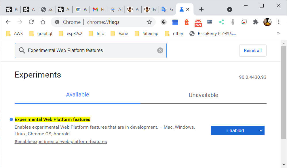
So first, you need Chrome.
Then you must enable WebSerial API, and do that, you must put in the browser input URL chrome://flags then search (with Ctrl+f) Experimental Web Platform features and enable It.
Then load the example given in the library webserial_3d, upload, and start It.
Now open this in the browser this url:
https://adafruit.github.io/Adafruit_WebSerial_3DModelViewer/
Select 9600 baud, click connect and select the correct device serial port.
The result is that you can change the orientation of the bunny with the movement of bno055.
This is a fantastic library, but I think it is appropriate to experiment with more complex management of the device with the help of interrupts. To do this, we will make use of another library in the next article.
Thanks
- BNO055 accelerometer, gyroscope, magnetometer with basic Adafruit library
- BNO055 for esp32, esp8266, and Arduino: wiring and advanced Bosch library
- BNO055 for esp32, esp8266, and Arduino: features, configuration, and axes remap
- BNO055: power modes, accelerometer, and motion interrupt
- BNO055 for esp32, esp8266, and Arduino: enable INT pin and accelerometer High G Interrupt
- BNO055 for esp32, esp8266, and Arduino: Gyroscope High Rate and Any Motion Interrupt