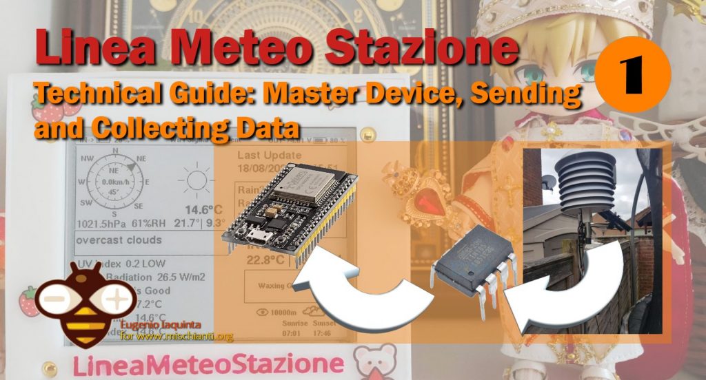
LineaMeteoStazione: Technical Guide Master Device, Sending and Collecting Data – 1
Guest post created with ♥ by Eugenio 🙂|
Introduction
This starting guide will talk about how it works LineaMeteoStazione, a bit more technically speaking.
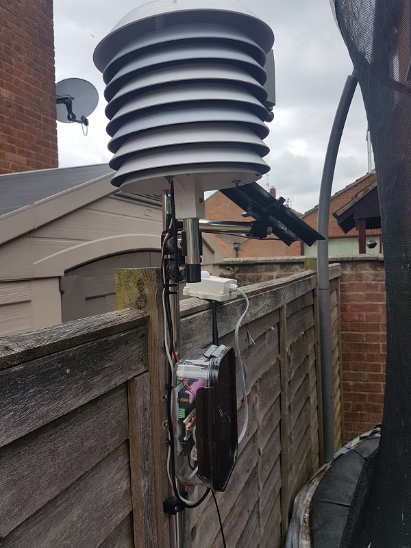
First of all, how did the idea of creating this type of Weather Station come to my mind? The idea came mainly because of my passion for observation regarding metereological phenomena and the environment in general. The thing was that I didn’t like to just have a weather station from the market, where you don’t know usually what type of sensors they are using or especially in regards to the solar shield that is often made in a way that you just need to replace it because the performance is just not enough. This is where I started to find a way to build my Weather Station which can use many different sensors and solar shields and is all manageable by users without reprogramming the unit!
Microcontroller ESP32 and Attiny85
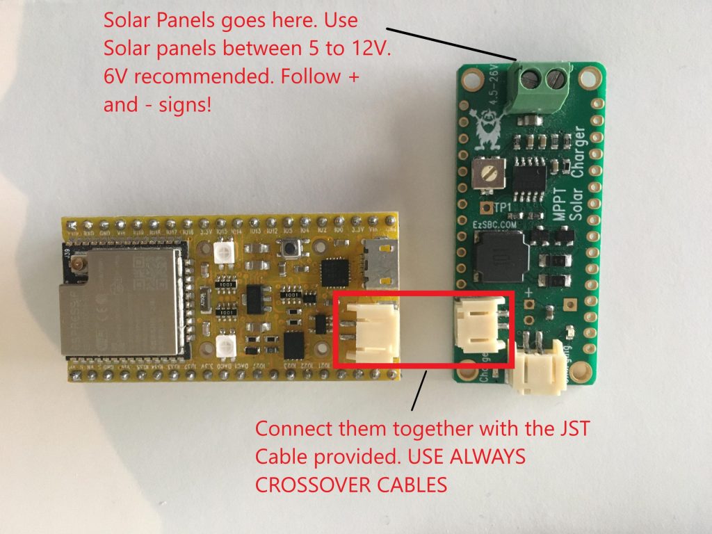
The first choice to make was the one regarding the microcontroller to collect the data. I decided to use the ESP32, since I was interested in WiFi functionality and fast CPU speed, in case I would need it. I decided to use the EZSBC development board because it has onboard accurate monitoring of the SOC of the battery using the LC709203F IC and communicating through I2C you can get the voltage and percentage of the Cell.
The board also use only 12uA while sleeping, which makes the board an excellent solution for developing a project and reducing power consumption. Since the Anemometer and Rain Gauge need constant monitoring to be accurate and the ESP32 need to go in Deep Sleep Mode to save energy I needed to find a way to constantly monitor the Rain Gauge and Anemometer but at the same time cut down the power consumption.
While there is also an option to program everything using the ULP processor of the ESP32, eventually I choose to use the Attiny85 as a solution to my problem. The ESP32 will manage the sending of the data via WiFi and the Attiny85 will collect the data from the rain gauge and anemometer and then send back the ESP32 when it requests the data.
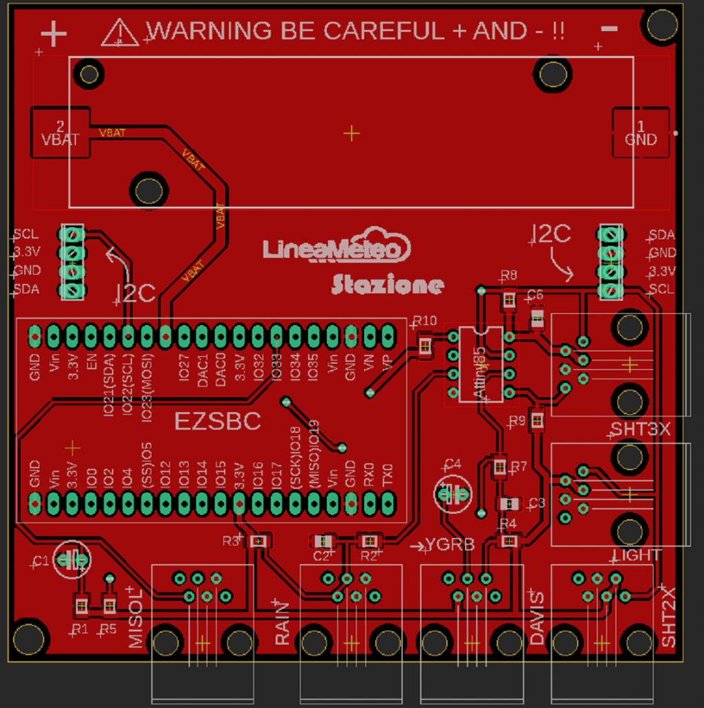
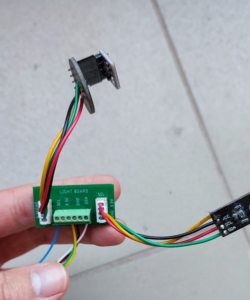
Here is the schematic and the PCB of all the components, including the light board, which is the one where the Lux and UV sensor are connected. HERE ON GITHUB THE FILES FOR EAGLE
Weather Station Autonomous with the Solar Charger and Battery Power
The main source of energy of the weather station is a lithium battery 18650 and the Sun with the use of a solar panel which size depends on the location you live in as explained in the general article regarding the weather station. I used a solar charger board to safely recharge the battery.
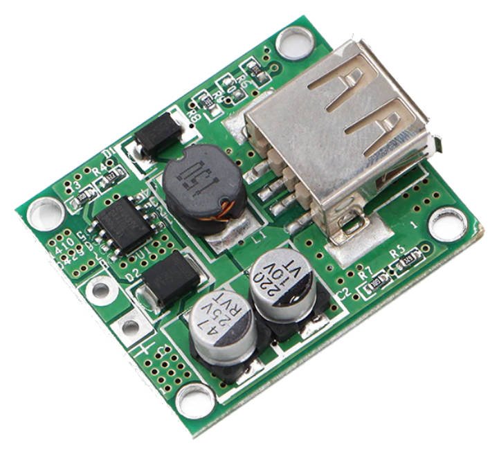
It is also possible to use a board like this one to recharge the battery through the USB port of the development board.
Collecting Data: ESP32, Attiny85 and Sensors
To collect data now we are going to look at the code used and how the code works. First of all, you need to have the Arduino IDE installed at least version 1.8.13 and you will need to install from the board manager of Arduino the ESP32 following those steps:
To install the ESP32 board in your Arduino IDE, follow these next instructions:
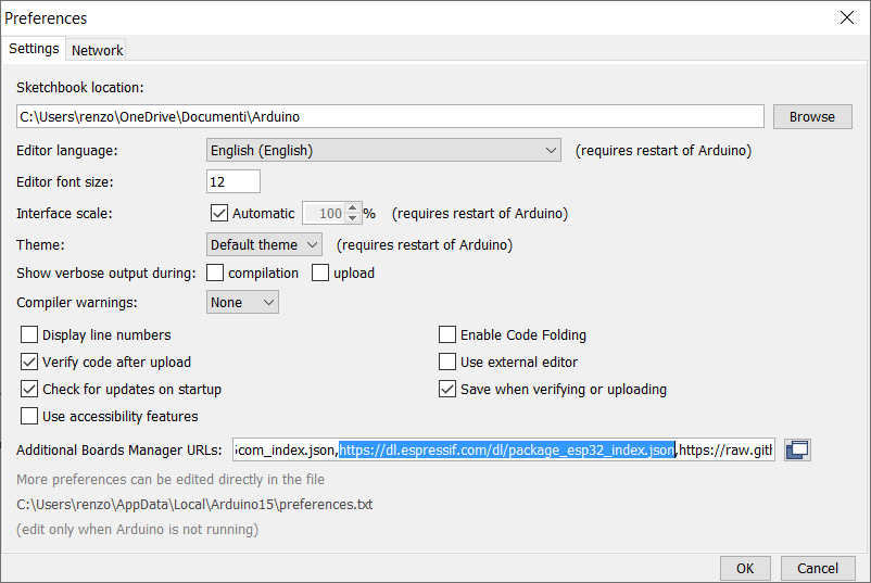
- In your Arduino IDE, go to File> Preferences
- Enter https://dl.espressif.com/dl/package_esp32_index.json into the “Additional Board Manager URLs” field. Then, click the “OK” button:
Note: if you already have the ESP8266 boards URL, you can separate the URLs with a comma as follows:https://dl.espressif.com/dl/package_esp32_index.json, http://arduino.esp8266.com/stable/package_esp8266com_index.json - Open the Boards Manager. Go to Tools > Board > Boards Manager…
- Search for ESP32 and press install button for the “ESP32 by Espressif Systems“ and wait for installation to finish.
You can find more information on this article “ESP32: pinout, specs and Arduino IDE configuration“.
Once installed, then you can program the ESP32 with this code.
The code works by first including the library that we are going to use:
///////////////////////////////LIBRARY DECLARATION////////////////////////////////////////
#include <Arduino.h>
#include <HTTPUpdate.h>
#include <WiFi.h>
#include <FirebaseESP32.h>       //https://github.com/mobizt/Firebase-ESP32
#include "ClosedCube_SHT31D.h"   //https://github.com/closedcube/ClosedCube_SHT31D_Arduino
#include "Adafruit_VEML6075.h"   //https://github.com/adafruit/Adafruit_VEML6075
#include "DFRobot_SHT20.h"       //https://github.com/DFRobot/DFRobot_SHT20
#include "LC709203F.h"      //https://github.com/EzSBC/ESP32_Bat_Pro/blob/main/LC709203F.zip
#include "Max44009.h"            //https://github.com/RobTillaart/Max44009
#include <WiFiManager.h>         // https://github.com/tzapu/WiFiManager
#include <Wire.h>
WiFiManager wifiManager;
#include <WebServer.h>
#include <ESPmDNS.h>
#include <HTTPUpdateServer.h>
#include <WiFiClient.h>
These all libraries can be found in the library manager of the Arduino IDE by searching them or following the link on the code, but some of them are already preinstalled if you installed the ESP module.
We create all the declarations and variables that we need to make the code works and we also need to insert the Firebase details which are the ones that you got from the article talking about the Weather Station. You can also insert your Ota drive details if you wish to use the Ota drive remote function that is explained widely HERE. You will need the API. When an update is required you will need to change the Version number.
//OTA REMOTE//
// To inject firmware info into binary file, You have to use following macro according to let
// OTAdrive to detect binary info automatically
#define ProductKey "" // Replace with your own APIkey
#define Version "1.0.1.1"
#define MakeFirmwareInfo(k, v) "&_FirmwareInfo&k=" k "&v=" v "&FirmwareInfo_&"
void update();

//OTA LOCAL//
WebServer httpServer(80);
HTTPUpdateServer httpUpdater;
const char* host = "esp32-webupdate";
String DEVICE1OTA;
unsigned long TIMEROTA;
//--------------------------------------------------------------------------------------//

///BATTERY OBJECT//
LC709203F gg;  // create a gas gauge object.

//DECLARATION SENSORS//
ClosedCube_SHT31D sht3xd;
DFRobot_SHT20    sht20;

//LIGHT SENSOR DEFINE//
Adafruit_VEML6075 uv = Adafruit_VEML6075();
Max44009 myLux(0x4A);

//I2C COMUNICATION ADDRESS//
const int I2CSlaveAddress = 8;      // I2C Address.

////////////////////*********FIREBASE DETAILS************///////////////////////////////////
#define FIREBASE_HOST ""                 // the project name address from firebase id
#define FIREBASE_AUTH ""            // the secret key generated from firebase
FirebaseData Weather;

//WIND DIRECTION//
#define WindDirectionDavis 32 // anemometer
#define WindDirectionMisol 33 // anemometer

////////////RAIN////////////////
byte PluvioFlag = 0; // detect interrupt of rain
byte rainrateI2C = 0;
byte rainrateMaxI2C = 0;
byte rainrateMaxI2CIntensity = 0;

////////////WIND/////////////////
int WindDirectionDavisValue;
int WindDirectionMisolValue;
byte Rotations;
byte GustRotations;

/////TIMING VARIALABLES//////
unsigned long timeout; // waiting for WiFi connection
bool res; // WiFi Status
unsigned int sampletime;
byte ReadByte = 0;
byte WiFiReset = 0;

//////////TEMPERATURE///////////
//SHT2X//
float tempSHT2x; // temperature in centigrade
float temp_f; // temperature in fahrenheit
int humiditySHT2x; // humidity variable

//SHT3X//
float temperatureSHT3x; // temperature in centigrade
int humiditySHT3x; // humidity variable

//////////////UV/////////////////
float UVindex; // variable UVindex
byte UVDETECT = 0;
The code works in a very simple way. The code first checks if a WiFi connection is available and if is not memorized on the device it enters in AP mode thanks to the WiFi manager library. After entering in AP mode it stays for 5 minutes waiting for a setup otherwise it will restart. It starts then by initialising the sensors. This is as we initialise the sensors using the library basic code. We also set the IC that monitors the battery status.
void InitSensors()
{
  sht20.initSHT20();                                  // Init SHT20 Sensor
  delay(100);
  sht20.checkSHT20();
  sht3xd.begin(0x44);
  sht3xd.readSerialNumber();
  if (!gg.begin()) {
    while (1) delay(10);
  }
  gg.setCellCapacity(LC709203F_APA_3000MAH);
  //gg.setAlarmVoltage(3.4);
  gg.setCellProfile( LC709203_NOM3p7_Charge4p2 ) ;
  if (UVDETECT == 0)
  {
    if (! uv.begin()) {
      UVDETECT = 1;
    }
  }
  if (UVDETECT == 0)
  {
    uv.setIntegrationTime(VEML6075_100MS);
    uv.setHighDynamic(false);
    uv.setForcedMode(false);
    uv.setCoefficients(2.22, 1.17,  // UVA_A and UVA_B coefficients
                       2.95, 1.58,  // UVB_C and UVB_D coefficients
                       0.004770, 0.006135); // UVA and UVB responses
  }
  myLux.setAutomaticMode();
}
Then in the initData() function as shown in the full code we check if we need to reset the WiFi or if there are any OTA updates and we read the bytes coming from the Attiny85. We also check the sample time to set when the data is sent to the server. Check from Firebase is very simple and can be done in an example code as below
  if (Firebase.getInt(Weather, "/Connection/DEVICE1/ResetWiFi"))
  {
    WiFiReset = Weather.to<int>();
  }
- Weather is the object of the Firebase that we created at the beginning of the code.
- ‘getInt’ is what type of Variable we are going to get.
And this is how we read the byte coming from the Attiny85 with the function declared in the code as ‘byte readTiny’
PluvioFlag = readTiny(I2CSlaveAddress);
In the loop, we read the sensors and we update the data to the Firebase using as an example this line of code:
Firebase.setInt(Weather, "/Time/Communication/PluvioFlag", PluvioFlag);
Program Attiny85 for collecting Anemometer and Rain Gauge Data
To program Attiny85 we can use an Arduino and Arduino IDE as explained in this article or in “ATtiny Programmer Board“. The code for the Attiny is below or you can find it HERE as well. The Attiny is programmed to monitor the interrupt coming from the rain gauge and the anemometer and to send the data to the ESP32 once requested. RAIN and WIND are the 2 ISR cycles. It sends the Rotations and maximum rotations detected in the last period before transmitting to the ESP32. It also calculates the rain rate depending on the timing passed between the 2 pulses and it sends the data of rain, rain rate and rain rate max to the ESP32. (See PluvioDataEngine() function)
To reduce consumption the Attiny stays in Idle mode with the sleepNow() function and is programmed at 1MHz clock frequency.
#include <TinyWireS.h>       // Requires fork by Rambo with onRequest support
//#include <avr/wdt.h>         // watchdog
#include <avr/sleep.h>
#include "PinChangeInterrupt.h"
// Requires headers for AVR defines and ISR function
//#include <avr/io.h>
//#include <avr/interrupt.h>

// Choose a valid PinChangeInterrupt pin of your Arduino board
#define INT_PINRAIN PB4
#define INT_PINANEMOMETER PB1
const int I2CSlaveAddress = 8;      // I2C Address.
byte ReadByte = 0;


////////////RAIN////////////////
volatile byte PluvioFlag = 0; // detect interrupt of rain
volatile byte RainFlag = 0; // detect interrupt of rain
volatile unsigned long ContactBounceTimeRain = 0; // Timer to avoid double counting in interrupt
float mmGoccia = 0.3; // tipping bucket count in mm
unsigned int gocce = 0; // tipping bucket movements
volatile unsigned long time1; // rain rate timing calculation
unsigned long PluvioStep = 0; // rain rate timing calculation
unsigned long PluvioOldStep = 0; // rain rate timing calculation
float rainrate = 0; // real-time rainrate
float rainrateMax = 0;
byte rainrateI2C = 0;
byte rainrateMaxI2C = 0;
byte rainrateMaxI2CIntensity = 0;

////////////WIND/////////////////
volatile byte Rotations; // cup rotation counter used in interrupt routine
volatile unsigned long ContactBounceTime = 0;
unsigned long calculation = 0; //millis() for sample time
unsigned int average = 3000; // sample time for wind speed
byte Gust; // gust variable


void setup() {
  sleepNow();
  //wdt_enable(WDTO_8S);               // Watchdog
  //pinMode(LED_PIN, OUTPUT);
  //cli();                            // Disable interrupts during setup
  //PCMSK |= (1 << INTERRUPT_PINRAIN);    // Enable interrupt handler (ISR) for our chosen interrupt pin (PCINT1/PB1/pin 6)
  //GIMSK |= (1 << PCIE);             // Enable PCINT interrupt in the general interrupt mask
  pinMode(INT_PINRAIN, INPUT);   // Set our interrupt pin as input with a pullup to keep it stable
  pinMode(INT_PINANEMOMETER, INPUT);   // Set our interrupt pin as input with a pullup to keep it stable
  //sei();                            //last line of setup - enable interrupts after setup
  attachPCINT(digitalPinToPCINT(INT_PINRAIN), RAIN, FALLING);
  attachPCINT(digitalPinToPCINT(INT_PINANEMOMETER), WIND, FALLING);
  TinyWireS.begin(I2CSlaveAddress);      // Begin I2C Communication
  TinyWireS.onRequest(transmit);         // When requested, call function transmit()
}


void loop() {
  sleepNow();
  if (millis() - calculation >= average)
  {
    calculation = millis();
    Rotations = 0;
  }
  if (Rotations > Gust)
  {
    Gust = Rotations;
  }
  if (RainFlag == 1) {
    RainFlag = 0;
    PluvioOldStep = PluvioStep;
    PluvioStep = time1;
    gocce++; // incrementa numero basculate
  }
  PluvioDataEngine();
  //wdt_reset();                          // feed the watchdog
  //delay(10);
}


//-------------------------------------------------------------------

void transmit() {
  switch (ReadByte) {
    case 0:
      TinyWireS.send(PluvioFlag);
      PluvioFlag = 0;
      ReadByte = 1;
      break;
    case 1:
      TinyWireS.send(Rotations);
      ReadByte = 2;
      break;
    case 2:
      TinyWireS.send(Gust);
      Gust = 0;
      ReadByte = 3;
      break;
    case 3:
      TinyWireS.send(rainrateI2C);
      ReadByte = 4;
      break;
    case 4:
      TinyWireS.send(rainrateMaxI2C);
      rainrateMaxI2C = 0;
      ReadByte = 5;
      break;
    case 5:
      TinyWireS.send(rainrateMaxI2CIntensity);
      rainrateMaxI2CIntensity = 0;
      ReadByte = 0;
      break;
  }
}

void RAIN()
{
  if ((millis() - ContactBounceTimeRain) > 250 ) { // debounce the switch contact.
    PluvioFlag++;
    RainFlag = 1;
    ContactBounceTimeRain = millis();
    time1 = millis();
  }
}

void WIND()
{
  if ((millis() - ContactBounceTime) > 15 ) { // debounce the switch contact.
    Rotations++;
    ContactBounceTime = millis();
  }
}

void PluvioDataEngine() {
  if (((PluvioStep - PluvioOldStep) != 0) && (gocce >= 2)) {
    if ((millis() - PluvioStep) > (PluvioStep - PluvioOldStep)) {
      rainrate = 3600 / (((millis() - PluvioStep) / 1000)) * mmGoccia;
      rainrateMax = rainrate / 10;
      if (rainrate < 1) {
        gocce = 0;
        rainrate = 0;
      }
    } else {
      rainrate = 3600 / (((PluvioStep - PluvioOldStep) / 1000)) * mmGoccia;
      rainrateMax = rainrate / 10;
    }
  } else {
    rainrate = 0.0;
  }
  if (rainrate > 255)
  {
    rainrateI2C = 255;
  }
  else
  {
    rainrateI2C = (byte)rainrate;
  }
  if (rainrateI2C > rainrateMaxI2C)
  {
    rainrateMaxI2C = rainrateI2C;
  }
  if (rainrateMax > rainrateMaxI2CIntensity)
  {
    rainrateMaxI2CIntensity = (byte)rainrateMax;
  }
}

void sleepNow()         // here we put the arduino to sleep
{
  /* Now is the time to set the sleep mode. In the Atmega8 datasheet
     http://www.atmel.com/dyn/resources/prod_documents/doc2486.pdf on page 35
     there is a list of sleep modes which explains which clocks and
     wake up sources are available in which sleep modus.
     In the avr/sleep.h file, the call names of these sleep modus are to be found:
     The 5 different modes are:
         SLEEP_MODE_IDLE         -the least power savings
         SLEEP_MODE_ADC
         SLEEP_MODE_PWR_SAVE
         SLEEP_MODE_STANDBY
         SLEEP_MODE_PWR_DOWN     -the most power savings
     For now, we want as much power savings as possible, so we
     choose the according
     sleep modus: SLEEP_MODE_PWR_DOWN
     Timer 2 overflow interrupt is only able to wake up the ATmega in PWR_SAVE
  */
  // disable ADC
  ADCSRA = 0;
  set_sleep_mode(SLEEP_MODE_IDLE);   // sleep mode is set here

  sleep_enable();          // enables the sleep bit in the mcucr register
  // so sleep is possible. just a safety pin

  sleep_mode();            // here the device is actually put to sleep!!
  // THE PROGRAM CONTINUES FROM HERE AFTER WAKING UP
  sleep_disable();         // first thing after waking from sleep:
  // disable sleep...
}
Links
- LineaMeteoStazione: Technical Guide Master Device, Sending and Collecting Data
- LineaMeteoStazione: Technical Guide Display
- LineaMeteoStazione: Technical Guide Receiver, Network and Manager Device
- LineaMeteoStazione: The Personalized WiFi Weather Station using ESP32, ESP8266 and Attiny85 with OTA
For the pre-assembled weather station or source of the material please email me Eugenio
eugenioiaquinta@outlook.it