WeAct Studio rp2040: high-resolution pinout and specs
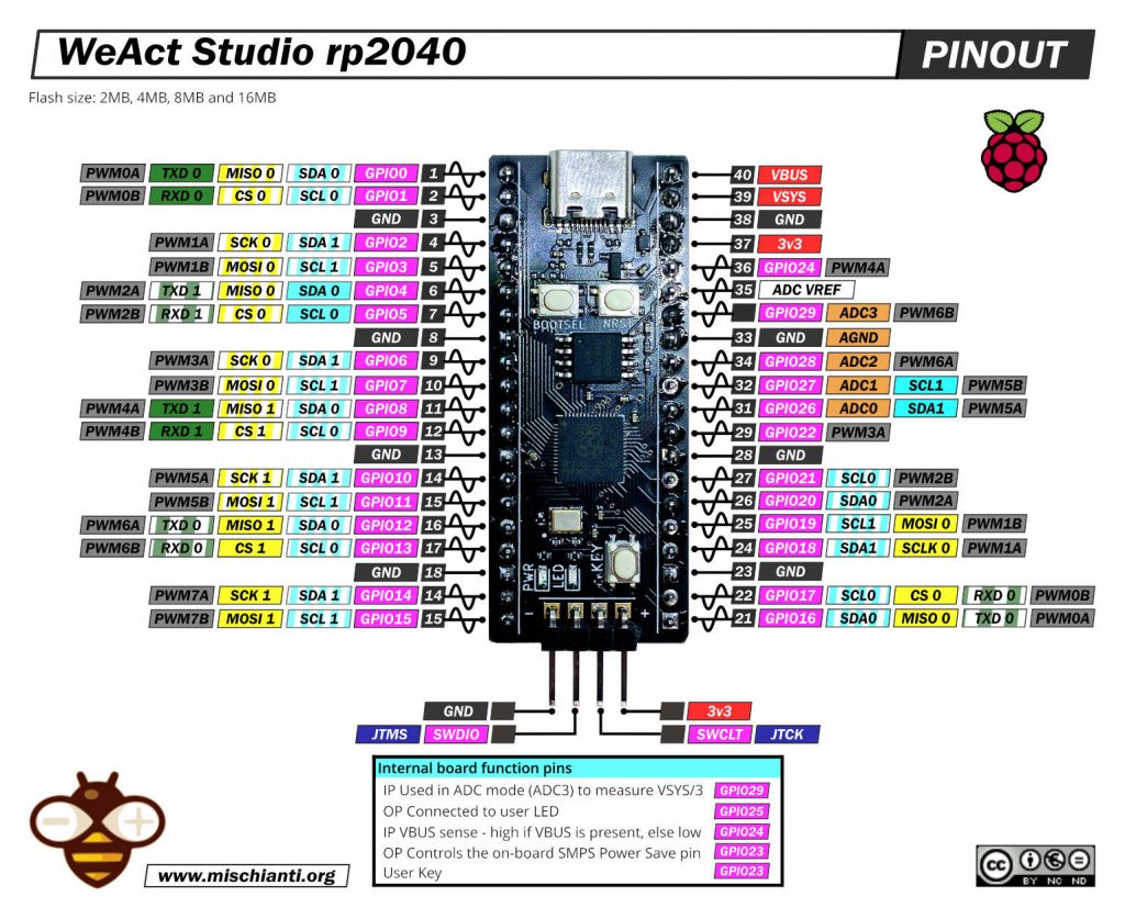
WeAct Studio rp2040 high resolution pinout image
Here my selection of rp2040 boards Official Pi Pico - Official Pi Pico W - Waveshare rp2040-zero - WeAct Studio rp2040
PINs
Power Pins
- VBUS – micro-USB input voltage
- VSYS – main system input voltage
- 3V3 – regulated 3.3V output
- GND – main ground reference
GPIO Pins
- GP0 to GP29 – General Purpose Input Output (GPIO) as well as Pulse Width Modulation (PWM)
I2C Pins
- SCL0 – I2C port 0 clock
- SDA0 – I2C port 0 data
- SCL1 – I2C port 1 clock
- SDA1 – IC2 port 1 data
SPI Pins
- SCLK0 – SPI port 0 clock
- MOSI0 – SPI port 0 data out
- MISO0 – SPI port 0 data in
- SCLK1 – SPI port 1 clock
- MOSI1 – SPI port 1 data out
- MISO1 – SPI port 1 data in
ADC Pins
- ADC0 – Analog to Digital Converter (ADC) 0
- ADC1 – Analog to Digital Converter (ADC) 1
- ADC2 – Analog to Digital Converter (ADC) 2
- ADC3 – Analog to Digital Converter (ADC) 3
Specs
WeAct Studio now have RP2040 boards available with 2MB, 4MB, 8MB or 16MB of flash at very reasonable prices.
The prices range from 3.85€ for the 2MB variant to €6.55 for the 16MB variant.
- RP2040 microcontroller chip designed by Raspberry Pi
- Dual-core Arm Cortex M0+ processor, flexible clock running up to 133 MHz
- 264KB of SRAM, and from 2MB to 16Mb of on-board Flash memory
- USB-C connector, keeps it up to date, easier to use
- USB 1.1 with device and host support
- Low-power sleep and dormant modes
- Drag-and-drop programming using mass storage over USB
- 29 × multi-function GPIO pins
- 2 × SPI, 2 × I2C, 2 × UART, 4 × 12-bit ADC, 16 × controllable PWM channels
- Accurate clock and timer on-chip
- Temperature sensor
- Accelerated floating-point libraries on-chip
- 8 × Programmable I/O (PIO) state machines for custom peripheral support
- BOOTSEL button and Reset button
- User button
- The debug port includes a 3V3 pin for powering the board
How to
- Raspberry Pi Pico and rp2040 boards: pinout, specs, and Arduino IDE configuration
- Raspberry Pi Pico and rp2040 boards: integrated LittleFS filesystem
- Raspberry Pi Pico and rp2040 board: ethernet w5500 with plain (HTTP) and SSL (HTTPS) requests
- Raspberry Pi Pico and rp2040 boards: WiFiNINA with ESP32 WiFi Co-Processor
- Raspberry Pi Pico and rp2040 boards: how to use SD card
- Dallas ds18b20
- Connecting the EByte E70 to Raspberry Pi Pico (rp2040) devices and a simple sketch example
rp2040 datasheet
Thanks
- Arduino
- esp8285
- esp8266
- ESP32
- DOIT ESP32 DEV KIT v1
- ESP32 DevKitC v4
- ESP32 WeMos LOLIN32
- ESP32 WeMos LOLIN32 Lite
- ESP32 WeMos LOLIN D32
- ESP32-wroom-32
- NodeMCU-32S
- ESP32-S
- ESP32-CAM
- ESP32-2432S028 (Cheap Yellow Display)
- ESP32-2432S032 (Cheap Yellow Display)
- ESP32 s2
- ESP32c3
- ESP32s3
- ESP32c6
- Arduino SAMD
- STM32
- Raspberry Pi


The pinout image is nice works! but the pinout has two errors
1. pin number 30~34 are misplaced and missing
2. the debug pin SWDIO and SWCLK (not SWCLT) are interchanged!
Hi,
30 and 34 have different layouts from Pico and SWDIO, and SWCLK are correctly placed, but I write SWCLT.
I’m going to fix It.
thanks, Renzo