Raspberry Pi Pico: high-resolution pinout and specs
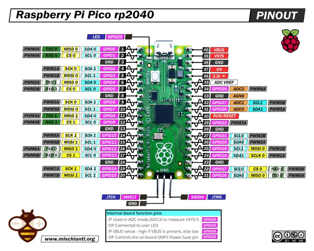
Raspberry Pi Pico high resolution pinout image
Here my selection of rp2040 devices Official Pi Pico - Official Pi Pico W - Waveshare rp2040-zero - WeAct Studio rp2040
PINs
Power Pins
- VBUS – micro-USB input voltage
- VSYS – main system input voltage
- 3V3 – regulated 3.3V output, 300mA max
- GND – main ground reference
- AGND – ground reference for GP26-29 and ADC0 and ADC1
GPIO Pins
- GP0 to GP28 – General Purpose Input Output (GPIO) as well as Pulse Width Modulation (PWM)
I2C Pins
- SCL0 – I2C port 0 clock
- SDA0 – I2C port 0 data
- SCL1 – I2C port 1 clock
- SDA1 – IC2 port 1 data
SPI Pins
- SCLK0 – SPI port 0 clock
- MOSI0 – SPI port 0 data out
- MISO0 – SPI port 0 data in
- SCLK1 – SPI port 1 clock
- MOSI1 – SPI port 1 data out
- MISO1 – SPI port 1 data in
ADC Pins
- ADC0 – Analog to Digital Converter (ADC) 0
- ADC1 – Analog to Digital Converter (ADC) 1
- ADC2 – Analog to Digital Converter (ADC) 2
Specs
Raspberry Pi Pico has been designed to be a low-cost yet flexible development platform for RP2040, with the following key features:
- Dual-core cortex M0+ at up to 133MHz
- On-chip PLL allows variable core frequency
- 264kB multi-bank high-performance SRAM
- External Quad-SPI Flash with eXecute In Place (XIP) and 16kB on-chip cache
- High-performance full-crossbar bus fabric
- On-board USB1.1 (device or host)
- 30 multi-function General Purpose IO (4 can be used for ADC)
- 1.8-3.3V IO Voltage (NOTE Pico IO voltage is fixed at 3.3V)
- 12-bit 500ksps Analogue to Digital Converter (ADC)
- Various digital peripherals
- 2 × UART, 2 × I2C, 2 × SPI, 16 × PWM channels
- 1 × Timer with 4 alarms, 1 × Real Time Counter
- 2 × Programmable IO (PIO) blocks, 8 state machines total
- Flexible, user-programmable high-speed IO
- Can emulate interfaces such as SD Card and VGA
- RP2040 microcontroller with 2MB Flash
- Micro-USB B port for power and data (and for reprogramming the Flash)
- 40 pin 21×51 ‘DIP’ style 1mm thick PCB with 0.1″ through-hole pins also with edge castellations
- Exposes 26 multi-function 3.3V General Purpose I/O (GPIO)
- 23 GPIO are digital-only, and three are ADC capable
- It can be surface mounted as a module
- 3-pin ARM Serial Wire Debug (SWD) port
- Simple yet highly flexible power supply architecture
- Various options for easily powering the unit from micro-USB, external supplies, or batteries
How to
- Raspberry Pi Pico and rp2040 boards: pinout, specs, and Arduino IDE configuration
- Raspberry Pi Pico and rp2040 boards: integrated LittleFS filesystem
- Raspberry Pi Pico and rp2040 board: ethernet w5500 with plain (HTTP) and SSL (HTTPS) requests
- Raspberry Pi Pico and rp2040 boards: WiFiNINA with ESP32 WiFi Co-Processor
- Raspberry Pi Pico and rp2040 boards: how to use SD card
- Dallas ds18b20
- Connecting the EByte E70 to Raspberry Pi Pico (rp2040) devices and a simple sketch example
Datasheet and schema
Thanks
- Arduino
- esp8285
- esp8266
- ESP32
- DOIT ESP32 DEV KIT v1
- ESP32 DevKitC v4
- ESP32 WeMos LOLIN32
- ESP32 WeMos LOLIN32 Lite
- ESP32 WeMos LOLIN D32
- ESP32-wroom-32
- NodeMCU-32S
- ESP32-S
- ESP32-CAM
- ESP32-2432S028 (Cheap Yellow Display)
- ESP32-2432S032 (Cheap Yellow Display)
- ESP32 s2
- ESP32c3
- ESP32s3
- Arduino SAMD
- STM32
- Raspberry Pi