ESP32: manage multiple Serial and logging for debugging – 3
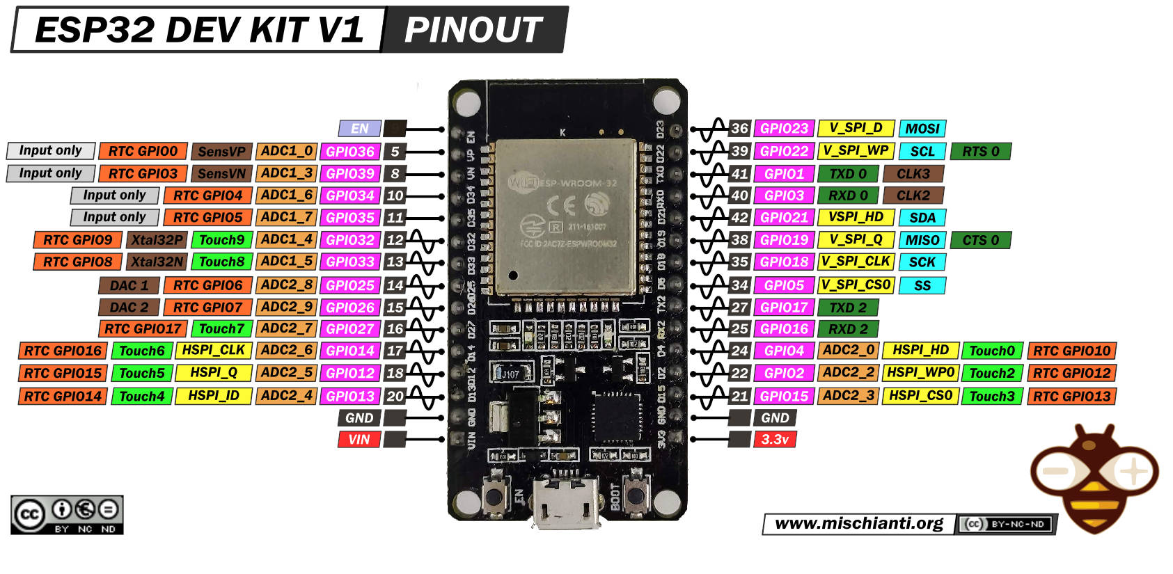
As you can see in the pinout diagram esp32 can have multiple UART, some are market as RX2 and TX2.
You can buy the esp32 from my selection here ESP32 Dev Kit v1 - TTGO T-Display 1.14 ESP32 - NodeMCU V3 V2 ESP8266 Lolin32 - NodeMCU ESP-32S - WeMos Lolin32 - WeMos Lolin32 mini - ESP32-CAM programmer - ESP32-CAM bundle - ESP32-WROOM-32 - ESP32-S - ESP32-WROOM-32 - ESP32 2.8 Inch Touch ESP32-2432S028
We are going to see an ESP32 DOIT DEV KIT v1
And a better ESP32 the WeMos LOLIN32.
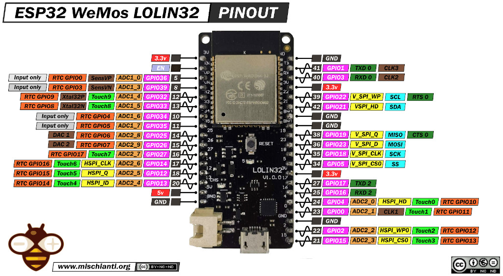
This pins can be used at to transmit core debug information or like a classic serial named Serial2.
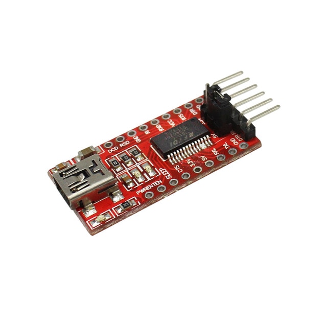
To connect, naturally, you must use a USB to TTL converter, you can find it at 1$.
Exists more expensive FT232RL or FT232 module, but a CH340G or CH340 working very good.
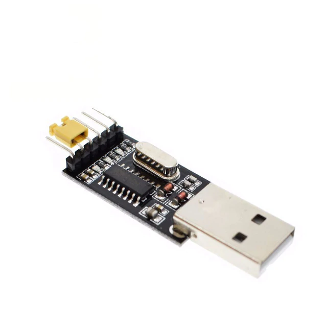
You can find here USB to TTL CH340G - USB to TTL FT232RL
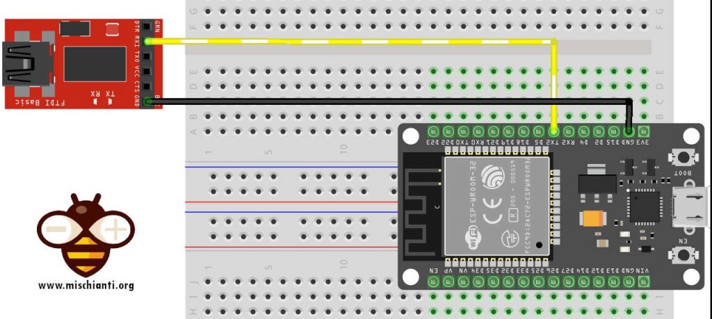
Connection schema is very simple, here for DOIT DEV KIT v1
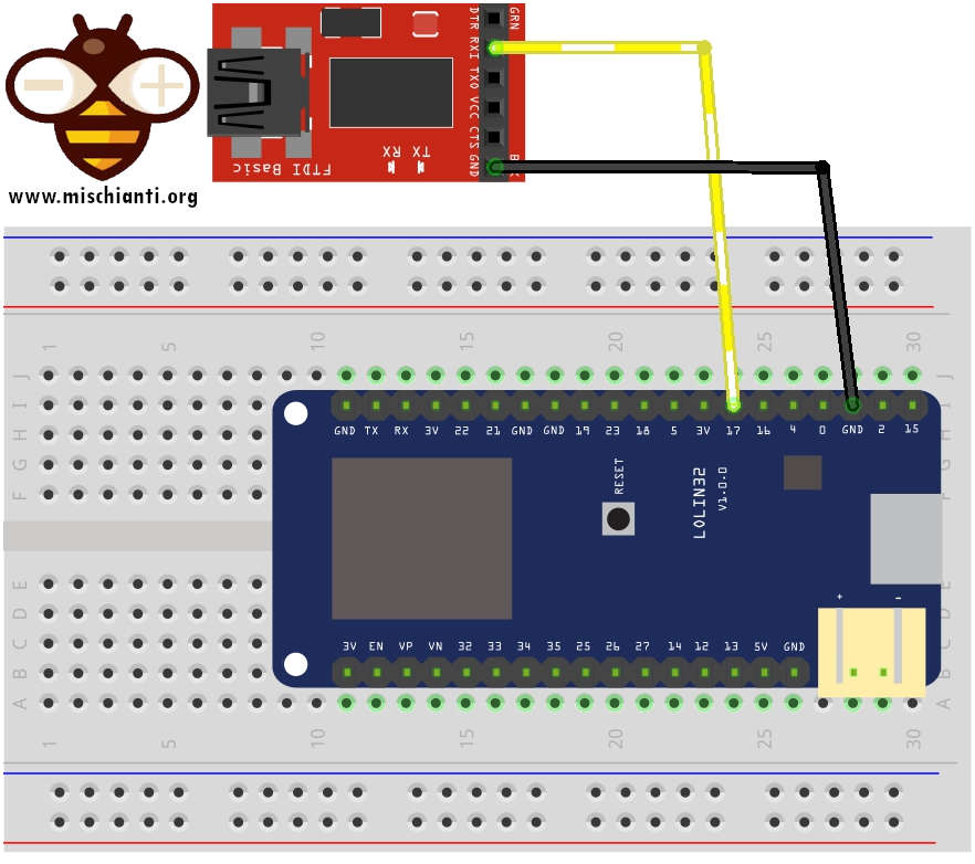
and here for WeMos LOLIN32
Example
/*
 *  ESP32 DOIT DEV KIT v1 - ESP32 WeMos LOLIN32
 *  Debug on standard Serial and Serial2 on GPIO17 pin
 *  by Mischianti Renzo <https://mischianti.org>
 *
 *  https://mischianti.org/
 *
 */
#include "Arduino.h"

void setup()
{
	Serial.begin(9600);
	Serial2.begin(9600);
}

int i = 0;
void loop()
{
	i++;
	Serial.print("Hi, I'm Serial on standard TX RX pin! --> ");
	Serial.println(i);
	Serial2.print("Hi, I'm Serial2 on GPIO17! --> ");
	Serial2.println(i);
	delay(1000);
}
Here the serial monitor on standard UART (USB connection).
Hi, I'm Serial on standard TX RX pin! --> 1
Hi, I'm Serial on standard TX RX pin! --> 2
Hi, I'm Serial on standard TX RX pin! --> 3
Hi, I'm Serial on standard TX RX pin! --> 4
Here the serial monitor on Serial2 (USB to TTL converter).
Hi, I'm Serial2 on GPIO17! --> 1
Hi, I'm Serial2 on GPIO17! --> 2
Hi, I'm Serial2 on GPIO17! --> 3
Hi, I'm Serial2 on GPIO17! --> 4
Core debug
You can activate in Tools --> Debug level the logging at build time. This flag can activate low level system file and library log, the level are
- None
- Error
- Warn
- Info
- Debug
- Verbose
I write they in hierarchical order, so if you select None, no logs are shows, if you select Verbose all logs are shows.
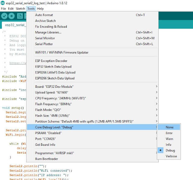
But set the core Debug Level is not sufficient you must enable log on your serial:
Serial2.setDebugOutput(true);
And you can use the core debug level for your project also, the commands are one for every log level:
	log_v("Verbose");
	log_d("Debug");
	log_i("Info");
	log_w("Warning");
	log_e("Error");
Than here a simple sketch to test they:
/*
 *  ESP32 DOIT DEV KIT v1 - ESP32 WeMos LOLIN32
 *  Debug on standard Serial and Serial2 on GPIO17 pin
 *  And logging on Serial2
 *  You must set log level on option of your IDE
 *  by Mischianti Renzo <https://mischianti.org>
 *
 *  https://mischianti.org/
 *
 */
#include "Arduino.h"
#include <WiFi.h>

#define STA_SSID "<YOUR-SSID>"
#define STA_PASS "<YOUR-PASSWD>"

#include "esp32-hal-log.h"

void setup() {
	Serial.begin(9600);
	Serial2.begin(9600);
	Serial2.setDebugOutput(true);

	Serial2.println("START WIFI");
	WiFi.begin(STA_SSID, STA_PASS);

    while (WiFi.status() != WL_CONNECTED) {
        delay(500);
        Serial2.print(".");
    }

    Serial2.println("");
    Serial2.println("WiFi connected");
    Serial2.println("IP address: ");
    Serial2.println(WiFi.localIP());
    delay(1000);
}

int i = 0;
void loop() {
	i++;
	Serial.print("Hi, I'm Serial on standard TX RX pin! --> ");
	Serial.println(i);
	delay(100);
	Serial2.print("Hi, I'm Serial2 on GPIO17! --> ");
	Serial2.println(i);
	delay(1000);

	log_v("Verbose");
	log_d("Debug");
	log_i("Info");
	log_w("Warning");
	log_e("Error");
	delay(5000);
}
Than if you compile and upload the sketch with log level set to Info you obtain this result on Serial and Serial2
START WIFI
.
WiFi connected
IP address:
192.168.1.168
Hi, I'm Serial on standard TX RX pin! --> 1
Hi, I'm Serial2 on GPIO17! --> 1
[I][esp32_serial_serial2_log_test.ino:50] loop(): Info
[W][esp32_serial_serial2_log_test.ino:51] loop(): Warning
[E][esp32_serial_serial2_log_test.ino:52] loop(): Error
Hi, I'm Serial on standard TX RX pin! --> 2
Hi, I'm Serial2 on GPIO17! --> 2
[I][esp32_serial_serial2_log_test.ino:50] loop(): Info
[W][esp32_serial_serial2_log_test.ino:51] loop(): Warning
[E][esp32_serial_serial2_log_test.ino:52] loop(): Error
But if you upload sketch with Verbose:
START WIFI
[D][WiFiGeneric.cpp:337] _eventCallback(): Event: 0 - WIFI_READY
[D][WiFiGeneric.cpp:337] _eventCallback(): Event: 2 - STA_START
[D][WiFiGeneric.cpp:337] _eventCallback(): Event: 4 - STA_CONNECTED
[D][WiFiGeneric.cpp:337] _eventCallback(): Event: 7 - STA_GOT_IP
[D][WiFiGeneric.cpp:381] _eventCallback(): STA IP: 192.168.1.168, MASK: 255.255.255.0, GW: 192.168.1.1
.
WiFi connected
IP address:
192.168.1.168
Hi, I'm Serial on standard TX RX pin! --> 1
Hi, I'm Serial2 on GPIO17! --> 1
[V][esp32_serial_serial2_log_test.ino:48] loop(): Verbose
[D][esp32_serial_serial2_log_test.ino:49] loop(): Debug
[I][esp32_serial_serial2_log_test.ino:50] loop(): Info
[W][esp32_serial_serial2_log_test.ino:51] loop(): Warning
[E][esp32_serial_serial2_log_test.ino:52] loop(): Error
Hi, I'm Serial on standard TX RX pin! --> 2
Hi, I'm Serial2 on GPIO17! --> 2
[V][esp32_serial_serial2_log_test.ino:48] loop(): Verbose
[D][esp32_serial_serial2_log_test.ino:49] loop(): Debug
[I][esp32_serial_serial2_log_test.ino:50] loop(): Info
[W][esp32_serial_serial2_log_test.ino:51] loop(): Warning
[E][esp32_serial_serial2_log_test.ino:52] loop(): Error
You can see that there are WiFi low level debug [D] log also, this because are set on WiFi library.
Thanks
- ESP32: pinout, specs and Arduino IDE configuration
- ESP32: integrated SPIFFS Filesystem
- ESP32: manage multiple Serial and logging
- ESP32 practical power saving
- ESP32 practical power saving: manage WiFi and CPU
- ESP32 practical power saving: modem and light sleep
- ESP32 practical power saving: deep sleep and hibernation
- ESP32 practical power saving: preserve data, timer and touch wake up
- ESP32 practical power saving: external and ULP wake up
- ESP32 practical power saving: UART and GPIO wake up
- ESP32: integrated LittleFS FileSystem
- ESP32: integrated FFat (Fat/exFAT) FileSystem
- ESP32-wroom-32
- ESP32-CAM
- ESP32: use ethernet w5500 with plain (HTTP) and SSL (HTTPS)
- ESP32: use ethernet enc28j60 with plain (HTTP) and SSL (HTTPS)
- How to use SD card with esp32
- esp32 and esp8266: FAT filesystem on external SPI flash memory
- Firmware and OTA update management
- Firmware management
- OTA update with Arduino IDE
- OTA update with Web Browser
- Self OTA uptate from HTTP server
- Non-standard Firmware update
- Integrating LAN8720 with ESP32 for Ethernet Connectivity with plain (HTTP) and SSL (HTTPS)
- Connecting the EByte E70 to ESP32 c3/s3 devices and a simple sketch example
- ESP32-C3: pinout, specs and Arduino IDE configuration
- Integrating W5500 with ESP32 Using Core 3: Native Ethernet Protocol Support with SSL and Other Features
- Integrating LAN8720 with ESP32 Using Core 3: Native Ethernet Protocol Support with SSL and Other Features
- Dallas ds18b20:
- Guide to I2C on ESP32: Communication with Heterogeneous 5V and 3.3V Devices, Additional Interface Management and Scanner
- Display
- Complete Guide: Using an ILI9341 Display with the TFT_eSPI Library
- Integrating Touch Screen Functionality with Your ILI9341 TFT Display
- SSD1683 eInk Display with GxEPD and ESP32 (and CrowPanel 4.2″ HMI): basics and configuration
- SSD1683 eInk Display with GxEPD and ESP32 (and CrowPanel 4.2″ HMI): fonts, shapes, and images
- ESP32 e Display eInk SSD1683: come realizzare una Semplice Stazione Meteo (anche su CrowPanel 4.2″ HMI) con le API di OpenWeatherMap
- How to Send Emails with Attachments on ESP32/ESP8266 (EMailSender v4.0.0 & STARTTLS)
- ESP32 High Performance FTP Server: A Deep Dive into the MultiFTPServer Library (v3.x)
- HC-SR04 Ultrasonic Sensor with ESP32 and Arduino: Complete Guide
- How to connect multiple HC-SR04 sensors with PCF8574 (3 methods)
- Fix slow HC-SR04 sensors with PCF8574: the hybrid approach trick [Guide]




In the first code block example inside the loop() function, serial1 is being referenced instead of serial 2.
Hi Jithesh,
thanks I fixed It.