
Seeed Studio XIAO rp2350: pinout, datasheet, schema, and specifications
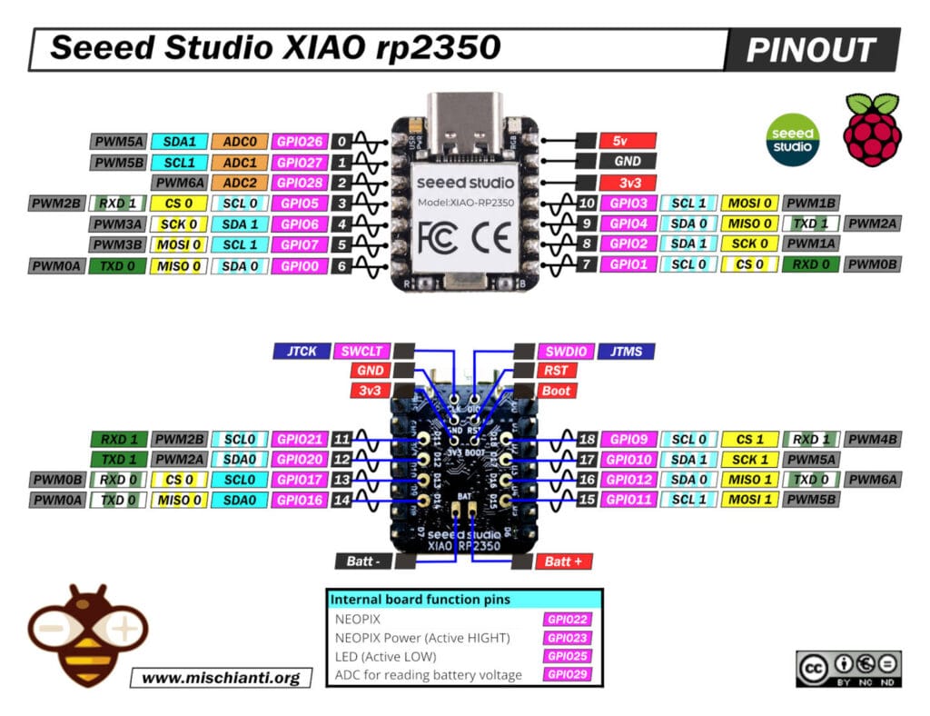
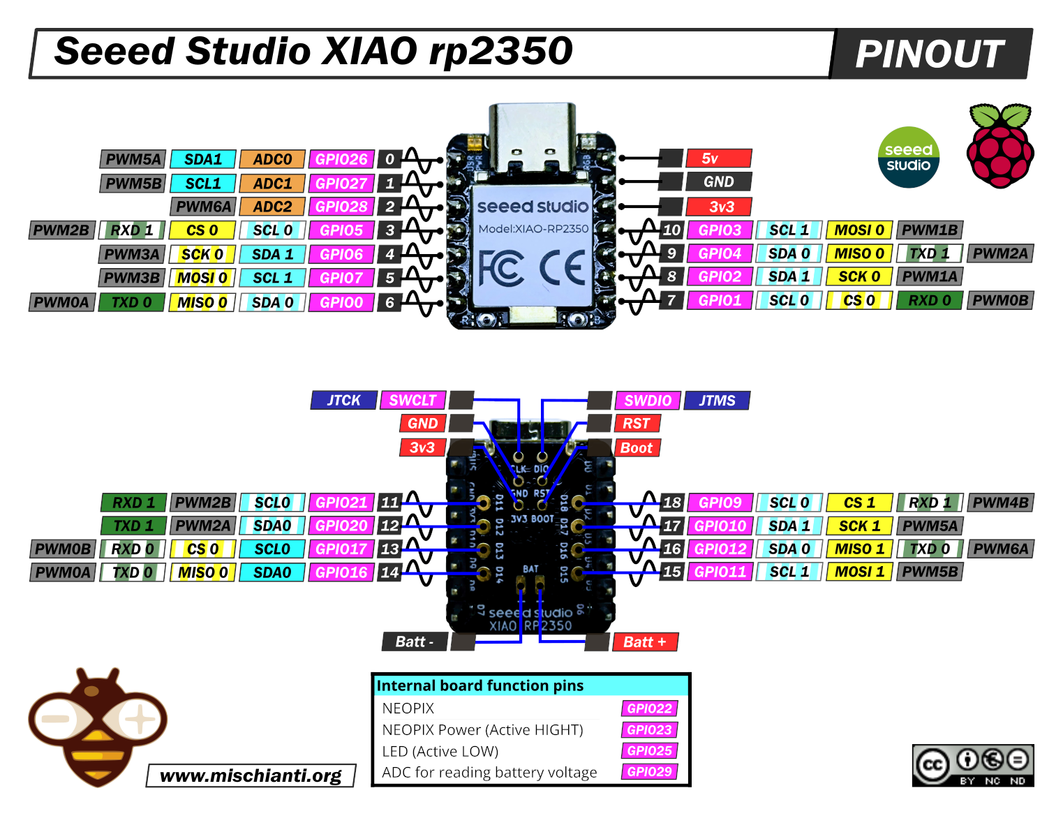
Here is the high-resolution pinout
Here you can find Seeed Studio devices All XIAO Series - XIAO accessories - XIAO AI Vision Camera
The Seeed Studio XIAO RP2350 is a high-performance, stamp-sized development board that integrates the powerful Raspberry Pi RP2350 microcontroller into the classic 21 x 17.8 mm XIAO form factor. It stands out for its unique dual-architecture capability, allowing developers to switch between dual Arm Cortex-M33 cores and dual Hazard3 RISC-V cores via software. With robust security features (TrustZone, Secure Boot), an integrated battery management system, and expanded I/O (19 GPIOs), it is designed to bridge the gap between rapid prototyping and secure, professional edge computing applications.
Technical Specifications
| Feature | Specification | Notes |
| MCU | Raspberry Pi RP2350 | Dual-core, Hybrid Architecture |
| Cores | 2x Cortex-M33 (Arm) OR 2x Hazard3 (RISC-V) | Selectable at boot, 150 MHz Clock |
| SRAM | 520 KB | 10 banks for concurrent access |
| Flash | 2 MB (External QSPI) | XIP (Execute In Place) supported |
| Dimensions | 21 x 17.8 mm | Classic XIAO form factor |
| Voltage | 3.3V (Logic) / 5V (USB VBUS) | IO is NOT 5V tolerant (max 3.6V) |
| Battery Mgmt | Integrated (Charge + Monitor) | Charge ~370mA. Standby ~50µA 1 |
| Board Logic | 3.3V |
Comprehensive Pinout Analysis (Extrapolated from Core)
The following data is extracted directly from the Arduino Core definitions used by the compiler.
Front Header Pins (D0 – D10)
| Pin | GPIO | Arduino Name | Primary Function | Alternate / Bus Defaults |
| D0 | 26 | A0 | Analog Input 0 | |
| D1 | 27 | A1 | Analog Input 1 | |
| D2 | 28 | A2 | Analog Input 2 | |
| D3 | 5 | D3 | Digital I/O | SPI0 CS (SS) |
| D4 | 6 | D4 | Digital I/O | Wire1 SDA (I2C1) |
| D5 | 7 | D5 | Digital I/O | Wire1 SCL (I2C1) |
| D6 | 0 | D6 | Digital I/O | Serial1 TX (UART0) |
| D7 | 1 | D7 | Digital I/O | Serial1 RX (UART0) |
| D8 | 2 | D8 | Digital I/O | SPI0 SCK |
| D9 | 4 | D9 | Digital I/O | SPI0 MISO |
| D10 | 3 | D10 | Digital I/O | SPI0 MOSI |
Bottom Solder Pads (D11 – D18)
These pins are critical for accessing the default I2C interface (Wire) and the second hardware SPI/Serial ports.
| Pin | GPIO | Arduino Name | Function | Critical Note (From Header File) |
| D11 | 21 | D11 | Serial2 RX | UART1 RX |
| D12 | 20 | D12 | Serial2 TX | UART1 TX |
| D13 | 17 | D13 | Wire SCL | Default I2C_SCL (I2C0) |
| D14 | 16 | D14 | Wire SDA | Default I2C_SDA (I2C0) |
| D15 | 11 | D15 | SPI1 MOSI | |
| D16 | 12 | D16 | SPI1 MISO | |
| D17 | 10 | D17 | SPI1 SCK | |
| D18 | 9 | D18 | SPI1 SS |
Special Internal Pins
| Name | GPIO | Definition in Core | Note |
| User LED | 25 | #define PIN_LED (25u) | Yellow. Active Low (typically). |
| RGB LED | 22 | Not defined in Core | WS2812B Addressable LED (Requires Neopixel lib). |
| RGB PWR | 23 | Implied by hardware | Must be set HIGH to power on the RGB LED. |
| V_BAT | 29 | Implicit Hardware | ADC3 (Internal) for voltage monitoring. |
Serial Communication
In the Arduino environment for the RP2350, “Serial” refers to three distinct interfaces. Understanding the difference is critical for debugging and connecting modules.
Serial (USB CDC)
- Physical Location: The USB-C connector.
- Type: Virtual Serial over USB (USB CDC).
- Usage: Used for the Serial Monitor in the Arduino IDE, debug
Serial.print()messages, and uploading code. - Note: It does not use any GPIO pins. It is purely a software-driven USB stack running on the RP2350.
Serial1 (Hardware UART0)
- Physical Location: Pins D6 (TX) and D7 (RX) on the front header.
- Type: Hardware UART (UART0 Peripheral).
- Usage: The primary port for connecting external modules like GPS, Bluetooth, or ESP8266 AT bridges.
- Performance: Fully hardware-driven with interrupts and FIFOs. It is independent of the USB connection.
Serial2 (Hardware UART1)
- Physical Location: Pads D12 (TX) and D11 (RX) on the bottom of the board.
- Type: Hardware UART (UART1 Peripheral).
- Usage: A completely independent second hardware serial port. Ideal for “Bridge” projects (e.g., reading a GPS on
Serial1and sending data to a cellular modem onSerial2). - Access: Requires soldering wires to the small pads on the back or using pogo pins.
Critical Engineering Tips & “Gotchas”
| Issue | Technical Detail (Based on Core Analysis) | Solution |
| The “Wire” Trap | The Arduino core defines Wire (the default I2C) on pins D14/D13 (Back Pads). Most users expect I2C on the front header (D4/D5). | • Use Wire1 for D4/D5 (Front).• OR Remap: Wire.setSDA(6); Wire.setSCL(7); Wire.begin(); |
| Expansion Board | The Seeed Expansion Board connects I2C to D4/D5. | If the RGB LED doesn’t light up, ensure you pinMode(23, OUTPUT); digitalWrite(23, HIGH);. |
| RGB Power | GPIO latch-up voltage (~2.1V) if the pin is an INPUT with PULL-DOWN. | The RGB LED often shares a power-enable pin (GPIO 23) to save battery power. |
| Errata E9 | GPIO latch-up voltage (~2.1V) if pin is INPUT with PULL-DOWN. | Do not use INPUT_PULLDOWN. Use external resistors or INPUT_PULLUP with inverted logic. |
| Battery Reading | The battery voltage is divided by 2 before the ADC. | Voltage Formula: V = (analogRead(29) * 3.3 / 4095) * 2. |
Arduino IDE Configuration & Usage
To compile for this board using the definitions analyzed above:
- Install Board Manager:
- File > Preferences > Additional Boards Manager URLs:
https://github.com/earlephilhower/arduino-pico/releases/download/global/package_rp2040_index.json
- Install Core:
- Tools > Board > Boards Manager: Search “Pico” -> Install “Raspberry Pi Pico/RP2040/RP2350 by Earle F. Philhower”.
- Select Board:
- Tools > Board > Raspberry Pi Pico/RP2040/RP2350 > Seeed XIAO RP2350.
- Select Architecture (Optional):
- Tools > CPU Architecture > Cortex-M33 (Default) or RISC-V (Hazard3).
- Pin Definition Validation:
- The settings in this report correspond to the
pins_arduino.hfile included in this core version.
- The settings in this report correspond to the
How To
- Raspberry Pi Pico and rp2040 boards: pinout, specs, and Arduino IDE configuration
- Raspberry Pi Pico and rp2040 boards: integrated LittleFS filesystem
- Raspberry Pi Pico and rp2040 board: ethernet w5500 with plain (HTTP) and SSL (HTTPS) requests
- Raspberry Pi Pico and rp2040 boards: WiFiNINA with ESP32 WiFi Co-Processor
- Raspberry Pi Pico and rp2040 boards: how to use SD card
- Dallas ds18b20
- Connecting the EByte E70 to Raspberry Pi Pico (rp2040) devices and a simple sketch example
Seeed Studio XIAO RP2350: Pros & Cons
| Pros | Cons |
| Dual-Architecture Power Unique ability to switch between Dual ARM Cortex-M33 and Dual RISC-V (Hazard3) cores, both running at 150 MHz. | No Wireless Connectivity Unlike the XIAO ESP32 or nRF52 series, this board has no Wi-Fi or Bluetooth capability onboard. |
| High Performance Significant upgrade over the RP2040 with faster clock speeds, FPU (Floating Point Unit), and DSP instructions. | Hardware Silicon Bug (Errata E9) Suffers from the RP2350-A2 “latching” bug where GPIOs get stuck at ~2.1V if used as Inputs with internal Pull-Downs enabled. |
| Enhanced Security Features ARM TrustZone, Secure Boot, and Signed Boot capabilities, making it suitable for professional/secure IoT devices. | Complex Pinout (Back Pads) Accessing the extra 8 GPIOs (including the second Serial/SPI port and default I2C) requires soldering to tiny pads on the bottom. |
| Integrated Battery Management Includes an onboard battery charger and voltage monitoring circuit (read via GPIO 29), simplifying wearable projects. | I2C “Wire” Conflict The default Arduino Wire (I2C) is mapped to the back pads. Users must manually remap pins to use I2C on the front header (D4/D5). |
| More I/O Pins Breaks out 19 GPIOs total (vs 14 on the RP2040 version), providing more flexibility for complex projects. | 3.3V Logic Only While the chip is technically 5V tolerant, the board design and compact traces generally dictate strict 3.3V logic. |
| Powerful PIO Features 3 PIO blocks (12 state machines), allowing for amazing custom protocols (HDMI, CAN, SDIO) without CPU load. | Limited Analog Inputs Only 3 ADC pins are available on the main header (D0, D1, D2), which is fewer than some competitors. |
| XIAO Ecosystem Fully compatible with the wide range of Seeed Studio XIAO expansion boards and Grove shields. | Tiny Reset/Boot Buttons The onboard buttons are extremely small and difficult to press without a tool. |
Simple RGB LED sketch
/*
  xiao_rp2350.ino
  NeoPixel single-LED color cycle demo.

  Brief: Cycles a single NeoPixel through red, green, blue, white and off.

  Author: Renzo Mischainti
  Reference: https://mischianti.org
*/

#include <Arduino.h>
#include <Adafruit_NeoPixel.h>

#define NEOPIXEL_POWER 23
#define PIN_NEOPIXEL 22
#define NUM_LEDS 1

// Initialize the NeoPixel object
Adafruit_NeoPixel pixels(NUM_LEDS, PIN_NEOPIXEL, NEO_GRB + NEO_KHZ800);

void setup() {
}

void loop() {
  // Turn RED
  // pixels.Color(Red, Green, Blue) -> Values from 0 to 255
  pixels.setPixelColor(0, pixels.Color(255, 0, 0));
  pixels.show();   // Push the data to the LED to update the color
  delay(1000);     // Wait for 1 second

  // Turn GREEN
  pixels.setPixelColor(0, pixels.Color(0, 255, 0));
  pixels.show();
  delay(1000);

  // Turn BLUE
  pixels.setPixelColor(0, pixels.Color(0, 0, 255));
  pixels.show();
  delay(1000);

  // Turn WHITE (All colors on)
  pixels.setPixelColor(0, pixels.Color(128, 128, 128));
  pixels.show();
  delay(1000);

  // Turn OFF
  pixels.clear();
  pixels.show();
  delay(500);
}
Datasheets
rp2350 datasheet
Schema
Thanks
- Arduino
- esp8285
- esp8266
- ESP32
- DOIT ESP32 DEV KIT v1
- ESP32 DevKitC v4
- ESP32 WeMos LOLIN32
- ESP32 WeMos LOLIN32 Lite
- ESP32 WeMos LOLIN D32
- ESP32-wroom-32
- NodeMCU-32S
- ESP32-S
- ESP32-CAM
- ESP32-2432S028 (Cheap Yellow Display)
- ESP32-2432S032 (Cheap Yellow Display)
- ESP32 s2
- ESP32c3
- ESP32s3
- ESP32c6
- Arduino SAMD
- STM32
- Raspberry Pi
- Silicon Labs
- Seeed Studio XIAO MG24 Sense


