ESP32 practical power saving: deep sleep and hibernation – 3
The most common power-saving mode for ESP32 is deep sleep, and here we will see what deep sleep is and the difference between hibernate variants.
A hibernation-like sleep modem is a logical definition that you have to manage. There is no specific command, it is “activated” by applying a certain logic, and since this mode offers excellent advantages, it can push you to change the logic of your code.
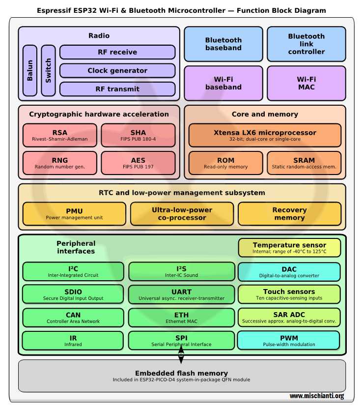
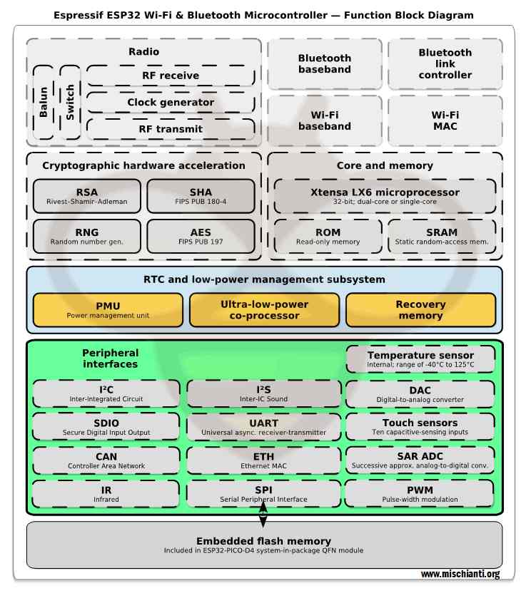
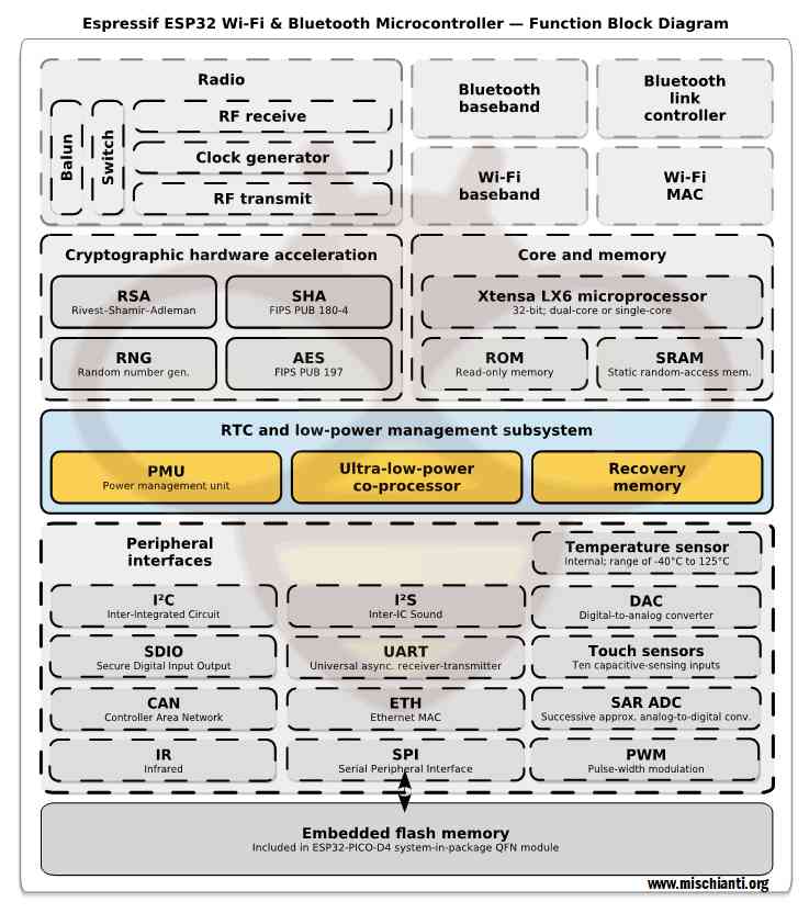
In deep sleep mode, CPUs, most of the RAM, and all the digital peripherals, managed from the clock of the Advanced Peripheral Bus (APB_CLK), are powered off. The only parts of the chip which can still be powered on are real-time clock (RTC) controller, RTC peripherals, Ultra-Low Power (ULP) coprocessor, and RTC memories (slow and fast).
In this table from the datasheet of esp32, there is information about group sleep mode.
| Power mode | Description | Power consumption | ||
Active (RF working) |
Wi-Fi Tx packet |
78 mA ~ 90 mA without communication For TX RX more info in the next table |
||
| Wi-Fi/BT Tx packet | ||||
| Wi-Fi/BT Rx and listening | ||||
Modem-sleep |
The CPU is powered on. |
240 MHz * | Dual-core chip(s) | 30 mA ~ 68 mA |
| Single-core chip(s) | N/A | |||
| 160 MHz * | Dual-core chip(s) | 27 mA ~ 44 mA | ||
| Single-core chip(s) | 27 mA ~ 34 mA | |||
| Normal speed: 80 MHz | Dual-core chip(s) | 20 mA ~ 31 mA | ||
| Single-core chip(s) | 20 mA ~ 25 mA | |||
| Light-sleep | – | 0.8 mA | ||
Deep-sleep |
The ULP co-processor is powered on. | 150 µA 100 µA @1% duty 10 µA | ||
| ULP sensor-monitored pattern | ||||
| RTC timer + RTC memory | ||||
| Hibernation | RTC timer only | 5 µA | ||
| Power off | CHIP_PU is set to low level, the chip is powered off. | 1 µA | ||
Deep sleep
Deep sleep is the most efficient way to put your device to sleep. Still, there is a big difference from light sleep, making it less usable. The state is cleared, so if you had set a variable when restarting your device, the variable is reset, and the program restarted from the initial setup.
But you must pay attention; in my block diagram, I give color on peripheral because the only real difference from hibernate is what functional unit must remain active, here what write Espressif.
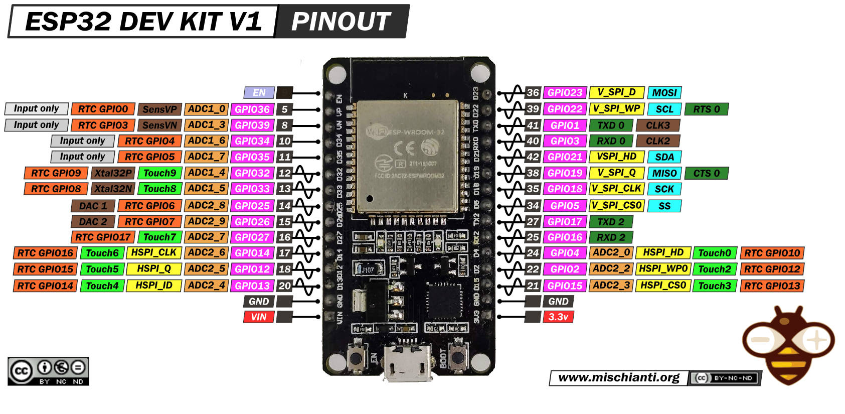
RTC IO module contains logic to trigger wakeup when one of RTC GPIOs is set to a predefined logic level. RTC IO is part of RTC peripherals power domain, so RTC peripherals will be kept powered on during deep sleep if this wakeup source is requested.
From Espressif documentation
So if we are going to use an external wake-up source, we will use a deep sleep; if we use nothing or only the RTC, we have a hibernation.
So here is a simple sketch to test deep sleep.
/*
 *  ESP32
 *  DEEP Sleep and wake up
 *  by Mischianti Renzo <https://mischianti.org>
 *
 *  https://mischianti.org/esp32-practical-power-saving-deep-sleep-and-hibernation-3/
 *
 */

#include <WiFi.h>
#include <BluetoothSerial.h>
#include "driver/adc.h"
#include <esp_bt.h>
#include <esp_wifi.h>
#include <esp_sleep.h>

#define STA_SSID "<YOUR-SSID>"
#define STA_PASS "<YOUR-PASSWD>"

BluetoothSerial SerialBT;

int variable = 0;

void setup() {
	Serial2.begin(115200);

	while(!Serial2){delay(500);}

  	SerialBT.begin("ESP32test"); //Bluetooth device name
	SerialBT.println("START BT");

	Serial2.println("START WIFI");
	WiFi.begin(STA_SSID, STA_PASS);

    while (WiFi.status() != WL_CONNECTED) {
        delay(500);
        Serial2.print(".");
    }

    Serial2.println("");
    Serial2.println("WiFi connected");
    Serial2.println("IP address: ");
    Serial2.println(WiFi.localIP());

    delay(1000);

    Serial2.print("Initial Variable value = ");
    Serial2.println(variable);

    variable += 10;

    Serial2.print("Variable updated = ");
    Serial2.println(variable);

    Serial2.println();
    Serial2.println("DEEP SLEEP ENABLED FOR 5secs");
    delay(100);

    esp_sleep_enable_timer_wakeup(5 * 1000 * 1000);
    // Pay attention to this command, with this wake up source
    // your device can't go to hibernate mode
    // but only deep sleep
    esp_sleep_enable_ext0_wakeup(GPIO_NUM_33,1);

    esp_deep_sleep_start();

    Serial2.println();
    Serial2.println("DEEP SLEEP WAKE UP");

    Serial2.print("Variable = ");
    Serial2.println(variable);
}

void loop() {

}

void disableWiFi(){
    adc_power_off();
	WiFi.disconnect(true);  // Disconnect from the network
	WiFi.mode(WIFI_OFF);    // Switch WiFi off

	Serial2.println("");
	Serial2.println("WiFi disconnected!");
}
void enableWiFi(){
	adc_power_on();
	WiFi.disconnect(false);  // Reconnect the network
	WiFi.mode(WIFI_STA);    // Switch WiFi off

	Serial2.println("START WIFI");
	WiFi.begin(STA_SSID, STA_PASS);

    while (WiFi.status() != WL_CONNECTED) {
        delay(500);
        Serial2.print(".");
    }

    Serial2.println("");
    Serial2.println("WiFi connected");
    Serial2.println("IP address: ");
    Serial2.println(WiFi.localIP());
}
void disableBluetooth(){
	btStop();
	esp_bt_controller_disable();
	delay(1000);
	Serial2.println("BT STOP");
}
When launching the sketch, we denote the first difference from light sleep, the variable state is not preserved in deep sleep mode, and the program flow restart from setup().
As you can see, the variable’s value is 0, and it is reset every time. And every time the esp32 comes out of deep sleep, it restarts from the initial. setup().
Now we are going to test this sketch with our three devices.
DOIT DEV KIT v1
For more information on the device, refer to “DOIT ESP32 DEV KIT v1 high resolution pinout and specs“.
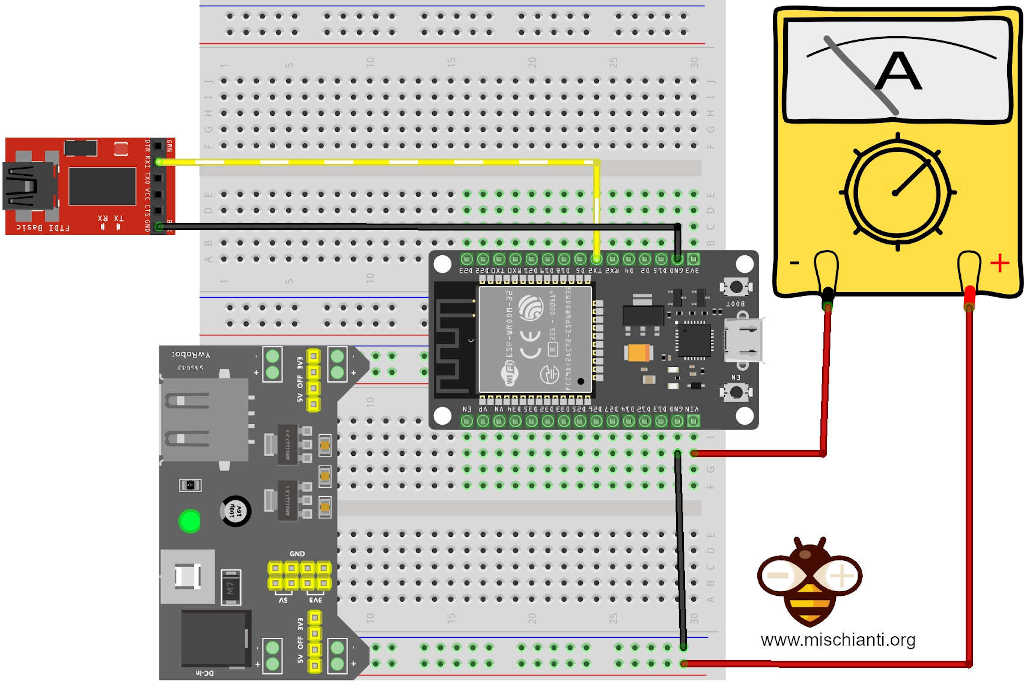
Here is the connection schema we used.
Power the esp32 to the 5v pin and GND pin with an external power supply and disconnect the USB. To log, we use the Serial2 port, but if you want to use the Serial port, you must only move the FTDI converter to the TX pin instead TX2 pin; you can’t use USB because it powers the device, and the multimeter gets the wrong amperage.
Data
Again the result is not good; this device in hibernate consumes 12.19mA, very, very, very far from the 150µA declared from Espressif.
As happened for light sleep at first, I was depressed, but from the experience of light sleep, I understand that the device I use is not designed for production; in a dev board, there is a lot of other components that can change the result, like LEDs, voltage regulators, etc.
I try to do the same test with two famous boards vendors that have devices with battery management and other features, not only for development.
TTGO T8
First, I want to try a TTGO, one of the most famous productor of this kind of device, with many variants; I use one of its better products, the TTGO T8.
The power source at 5v from the specified pin gives a lousy result of 9.63mA. Still, when powered only with a battery, the board excludes some functional units like led, voltage regulator, etc., so the same test with battery power reaches 4.56mA more likely result.
WeMos LOLIN32
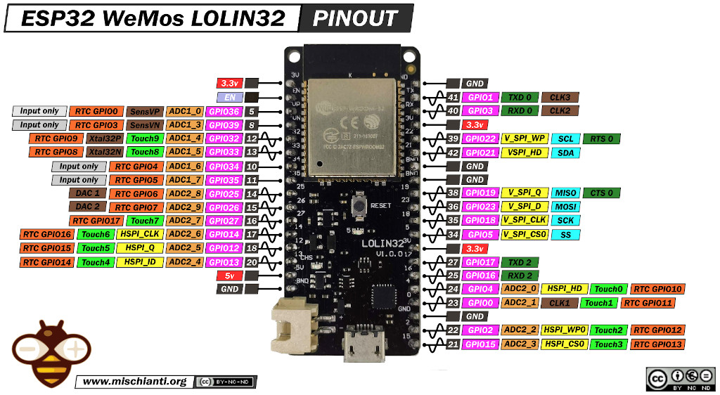
For more information on the device, refer to “ESP32 WeMos LOLIN32 high resolution pinout and specs“.
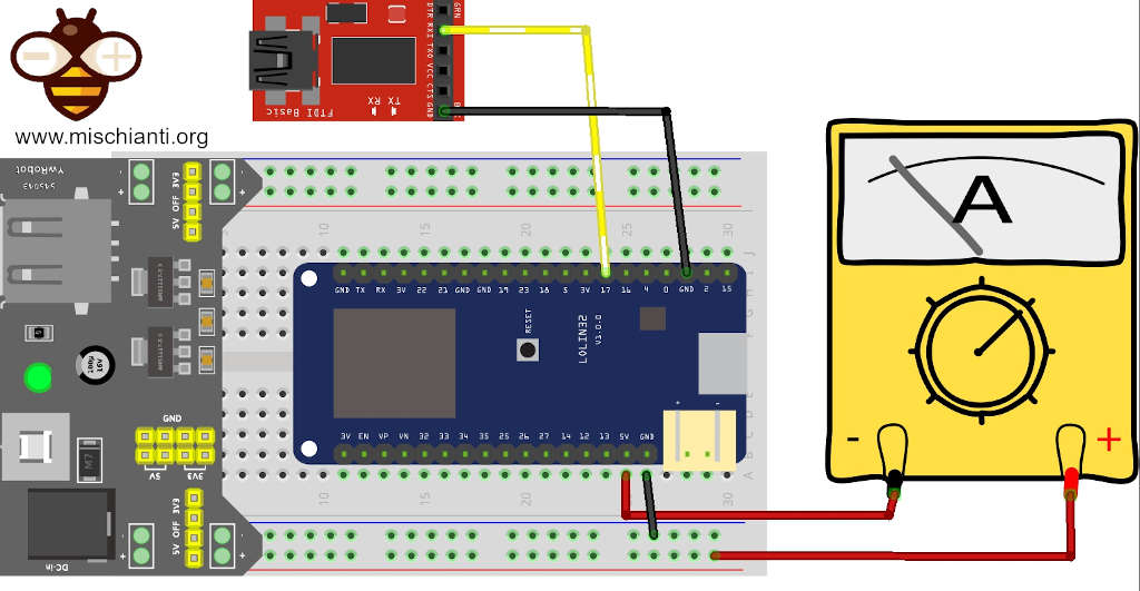
The wiring diagram
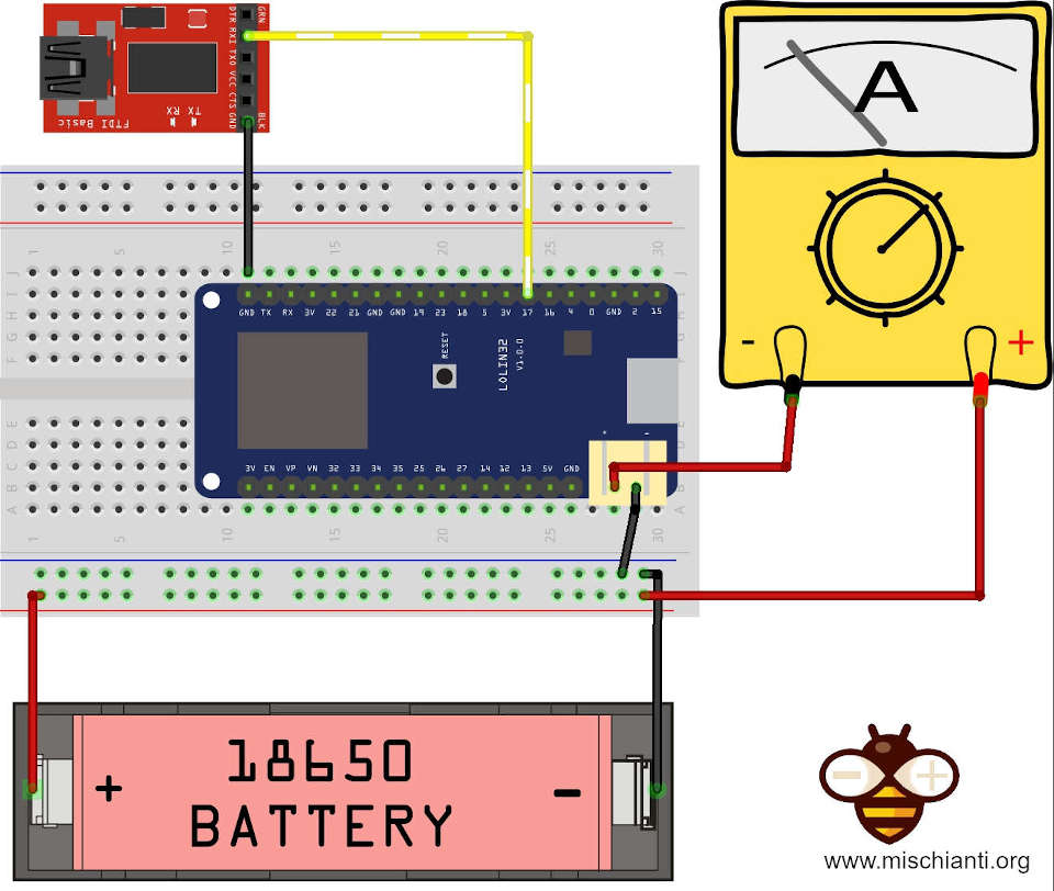
Wiring diagram with battery.
Then the WeMos LOLIN32; I love WeMos as a manufacturer, I believe I have a good set of devices, and these are very versatile with various sizes.
The result with the power source at 5v from the specified pin gives a better result, 2.92mA, and the board, when powered only with the battery, reaches 1.81mA.
| Device | Mode | Power |
|---|---|---|
| DOIT DEV KIT v1 | Power to VIN pin | 12.19mA |
| TTGO T8 | Power to 5V pin | 9.63mA |
| Power via Battery | 4.56mA | |
| WeMos LOLIN32 | Power via 5V pin | 2.92mA |
| Power via Battery | 1.81mA |
Hibernation
Hibernation is similar to deep sleep, but you have to give up some wake-up possibilities like external sources.
I create a simple sketch to test the hibernation performance
/*
 *  ESP32
 *  DEEP Sleep and wake up
 *  by Mischianti Renzo <https://mischianti.org>
 *
 *  https://mischianti.org/esp32-practical-power-saving-deep-sleep-and-hibernation-3/
 *
 */

#include <WiFi.h>
#include <BluetoothSerial.h>
#include "driver/adc.h"
#include <esp_bt.h>
#include <esp_wifi.h>
#include <esp_sleep.h>

#define STA_SSID "<YOUR-SSID>"
#define STA_PASS "<YOUR-PASSWD>"

BluetoothSerial SerialBT;

int variable = 0;

void setup() {
	Serial2.begin(115200);

	while(!Serial2){delay(500);}

  	SerialBT.begin("ESP32test"); //Bluetooth device name
	SerialBT.println("START BT");

	Serial2.println("START WIFI");
	WiFi.begin(STA_SSID, STA_PASS);

    while (WiFi.status() != WL_CONNECTED) {
        delay(500);
        Serial2.print(".");
    }

    Serial2.println("");
    Serial2.println("WiFi connected");
    Serial2.println("IP address: ");
    Serial2.println(WiFi.localIP());

    delay(1000);

    Serial2.print("Initial Variable value = ");
    Serial2.println(variable);

    variable += 10;

    Serial2.print("Variable updated = ");
    Serial2.println(variable);

    Serial2.println();
    Serial2.println("DEEP SLEEP ENABLED FOR 5secs");
    delay(100);

    esp_sleep_enable_timer_wakeup(5 * 1000 * 1000);
    esp_deep_sleep_start();

    Serial2.println();
    Serial2.println("DEEP SLEEP WAKE UP");

    Serial2.print("Variable = ");
    Serial2.println(variable);
}

void loop() {

}

void disableWiFi(){
    adc_power_off();
	WiFi.disconnect(true);  // Disconnect from the network
	WiFi.mode(WIFI_OFF);    // Switch WiFi off

	Serial2.println("");
	Serial2.println("WiFi disconnected!");
}
void enableWiFi(){
	adc_power_on();
	WiFi.disconnect(false);  // Reconnect the network
	WiFi.mode(WIFI_STA);    // Switch WiFi off

	Serial2.println("START WIFI");
	WiFi.begin(STA_SSID, STA_PASS);

    while (WiFi.status() != WL_CONNECTED) {
        delay(500);
        Serial2.print(".");
    }

    Serial2.println("");
    Serial2.println("WiFi connected");
    Serial2.println("IP address: ");
    Serial2.println(WiFi.localIP());
}
void disableBluetooth(){
	btStop();
	esp_bt_controller_disable();
	delay(1000);
	Serial2.println("BT STOP");
}
To put the devices in hibernation instead of Deep sleep, I remove the external wake-up source ext0. Remember ext0 put in deep sleep, but ext1 prevent the use of deep sleep.
DOIT DEV KIT v1
The hibernation has better results concerning deep sleep, and DEV KIT v1 consumes 3.46mA, but It’s very far from the 5µA declared from Espressif.
I try to do the same test with two famous boards vendor devices with battery management and other features, not only for dev.
TTGO T8
The result with the power source at 5v from the specified pin gives a bad result of 7.95mA, but the same test with battery power reach 3.33mA, relatively better than the first result and then DOIT DEV KIT v1.
WeMos LOLIN32
The result with the power source at 5v from the specified pin gives a better result of 1.26mA, but the board, when powered only with a battery, reaches 160µA, which is a perfect result.
Results
The data is unequivocal, and the DOIT DEV KIT v1 is the loser and the LOLIN32 winner. TTGO has the highest price cannot be considered up to par.
| Device | Mode | Power |
|---|---|---|
| DOIT DEV KIT v1 | Power to VIN pin | 3.46mA |
| TTGO T8 | Power to 5V pin | 7.95mA |
| Power via Battery | 3.33mA | |
| WeMos LOLIN32 | Power via 5V pin | 1.26mA |
| Power via Battery | 160µA |
Thanks
- ESP32: pinout, specs and Arduino IDE configuration
- ESP32: integrated SPIFFS Filesystem
- ESP32: manage multiple Serial and logging
- ESP32 practical power saving
- ESP32 practical power saving: manage WiFi and CPU
- ESP32 practical power saving: modem and light sleep
- ESP32 practical power saving: deep sleep and hibernation
- ESP32 practical power saving: preserve data, timer and touch wake up
- ESP32 practical power saving: external and ULP wake up
- ESP32 practical power saving: UART and GPIO wake up
- ESP32: integrated LittleFS FileSystem
- ESP32: integrated FFat (Fat/exFAT) FileSystem
- ESP32-wroom-32
- ESP32-CAM
- ESP32: use ethernet w5500 with plain (HTTP) and SSL (HTTPS)
- ESP32: use ethernet enc28j60 with plain (HTTP) and SSL (HTTPS)
- How to use SD card with esp32
- esp32 and esp8266: FAT filesystem on external SPI flash memory
- Firmware and OTA update management
- Firmware management
- OTA update with Arduino IDE
- OTA update with Web Browser
- Self OTA uptate from HTTP server
- Non-standard Firmware update
- Integrating LAN8720 with ESP32 for Ethernet Connectivity with plain (HTTP) and SSL (HTTPS)
- Connecting the EByte E70 to ESP32 c3/s3 devices and a simple sketch example
- ESP32-C3: pinout, specs and Arduino IDE configuration
- Integrating W5500 with ESP32 Using Core 3: Native Ethernet Protocol Support with SSL and Other Features
- Integrating LAN8720 with ESP32 Using Core 3: Native Ethernet Protocol Support with SSL and Other Features
- Dallas ds18b20:
- Guide to I2C on ESP32: Communication with Heterogeneous 5V and 3.3V Devices, Additional Interface Management and Scanner
- Display
- Complete Guide: Using an ILI9341 Display with the TFT_eSPI Library
- Integrating Touch Screen Functionality with Your ILI9341 TFT Display
- SSD1683 eInk Display with GxEPD and ESP32 (and CrowPanel 4.2″ HMI): basics and configuration
- SSD1683 eInk Display with GxEPD and ESP32 (and CrowPanel 4.2″ HMI): fonts, shapes, and images
- ESP32 e Display eInk SSD1683: come realizzare una Semplice Stazione Meteo (anche su CrowPanel 4.2″ HMI) con le API di OpenWeatherMap
- How to Send Emails with Attachments on ESP32/ESP8266 (EMailSender v4.0.0 & STARTTLS)
- ESP32 High Performance FTP Server: A Deep Dive into the MultiFTPServer Library (v3.x)
- Ultra WideBand (Positioning system)
- Reyax RYUW122_Lite (UWB): Pinout, Datasheet, Schema & Specs
- Precision Indoor Positioning (cm) with UWB, ESP32 & Arduino: Hardware & Basics
- UWB Indoor Positioning: Standard Architecture (Anchor & Tag) with RYUW122
- Standalone UWB Positioning: The “IPS” Reverse Architecture (GPS-like) with RYUW122
- HC-SR04 Ultrasonic Sensor with ESP32 and Arduino: Complete Guide
- How to connect multiple HC-SR04 sensors with PCF8574 (3 methods)
- Fix slow HC-SR04 sensors with PCF8574: the hybrid approach trick [Guide]





Hi, thanks for the info!
You have tried “rtc_gpio_isolate(GPIO_NUM_12);” to achieve better result?
Hi Poky,
I didn’t try that command, in the specs seems that It isn’t supported by all esp32, and I think reduce only the pull up/down current to the GPIO.
Bye Renzo
According to the latest doc, I think they changed it to use esp_sleep_config_gpio_isolate()
“For example, on ESP32-WROVER module, GPIO12 is pulled up externally. GPIO12 also has an internal pulldown in the ESP32 chip. This means that in deep sleep, some current will flow through these external and internal resistors, increasing deep sleep current above the minimal possible value.”
Hi poky,
the isolate in theory don’t drastically change the power consumption, because remove only the pull up/down. (I explain how to preserver this internal status in the next chapter).
Bye Renzo
Also, the spec says: “Hibernation mode: The internal 8-MHz oscillator and ULP co-processor are disabled. The RTC
recovery memory is powered down. Only one RTC timer on the slow clock and certain RTC GPIOs are
active. The RTC timer or the RTC GPIOs can wake up the chip from the Hibernation mode”
Why wake from the ext0 have such big impact?
Hi Poky,
in the documentation seems that the RTC timer (that do a perpetual cycle), used to listening the change on GPIO, is very hungry of resources.
Bye Renzo
There are two external wakeups, ext0 and ext1
External wake up doc
The interesting thing is that in ext0: “RTC IO is part of RTC peripherals power domain, so RTC peripherals will be kept powered on during deep sleep if this wakeup source is requested”
But in ext1: “This wakeup source is implemented by the RTC controller. As such, RTC peripherals and RTC memories can be powered down in this mode. However, if RTC peripherals are powered down, internal pullup and pulldown resistors will be disabled.”
Does it mean if you want to enter the hibernation mode, just need ext1 with external resistors?
Hi Poky,
yes, you can use ext1 to go in hibernation, you must set a bit mask and set one of this option:
– wake up if any of the selected pins is high (ESP_EXT1_WAKEUP_ANY_HIGH)
– wake up if all the selected pins are low (ESP_EXT1_WAKEUP_ALL_LOW)
The internal pull up pull down are needed to preserve the status of the pin in sleep mode, for example to manage my e32 I must keep the HIGH state to M0 and M1 pins and I use interna pull up, but if I don’t want manage internal pull up I must add an external resistor.
But the commands
gpio_pullup_dis(gpio_num);
gpio_pulldown_en(gpio_num);
are very usefully to manage that.
Bye Renzo
If you happened to have time to measure the current consumption with ext1. and both internal/external resistors that would be helpful! Cheers!
Hehehe, I try but now I’m very busy. I need help to do all.
Bye Renzo
Great articles. I just don’t understand the most important thing. Where in the code are the Disable WIFI, Anable WIFI & BT calls?
Hi Pae,
It’s the first article.
ESP32 practical power saving manage WiFi sleep and CPU frequency
Bye Renzo
Thank you. And two more problems. The code after compilation in arduino ide 2.0 does not fit in the memory of esp32 doit ver1. And one more thing: it doesn’t output the value of variable to serial. Could you please cite your logs in the article?
Hi Pae,
I think there is another problem, the program surely fits on memory.
For the Serial, It’s strange. Check the connection of external FDTI for Serial2.
Bye Renzo