
Integrating Touch Screen Functionality with Your ILI9341 TFT Display
In our previous article, “Using an ILI9341 Display with the TFT_eSPI Library”, we explored the capabilities of the ILI9341 TFT display. We covered everything from basic initialization and drawing graphics to configuring the library and wiring the display with an ESP32. Building on that foundation, this article takes the next step by integrating touchscreen functionality into your project. With the addition of touch, you can create interactive interfaces—such as virtual keypads and control panels—to further enhance your designs.
Before diving into the touch-specific details, let’s review the wiring diagrams from the previous article to ensure that our hardware setup remains consistent.
Wiring
For this test, we will use a DOIT ESP32 DevKit V1. This device is widely used and simple.
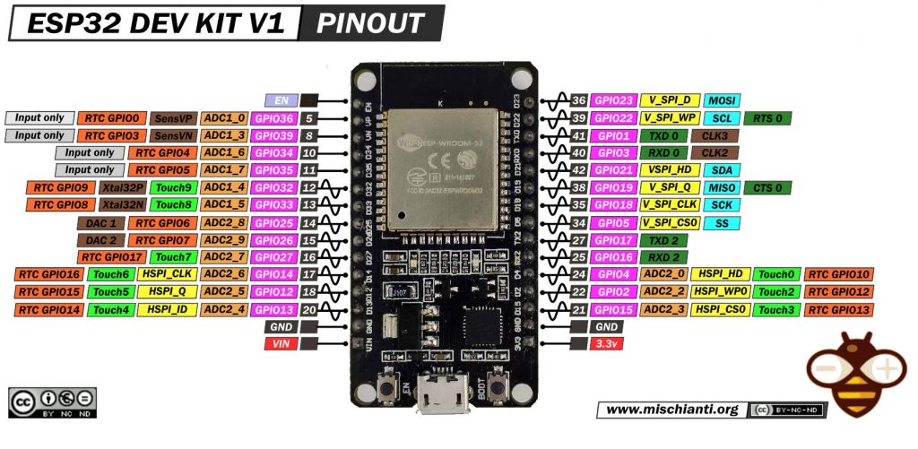
Here where to buy my selection of esp32 ESP32 Dev Kit v1 - TTGO T-Display 1.14 ESP32 - NodeMCU V3 V2 ESP8266 - NodeMCU ESP-32S - WeMos Lolin32 - WeMos Lolin32 mini - ESP32-CAM programmer - ESP32-CAM bundle - ESP32-WROOM-32 - ESP32-S - ESP32-WROOM-32 - ESP32 2.8 Inch Touch ESP32-2432S028
ILI9143 has various form factors.
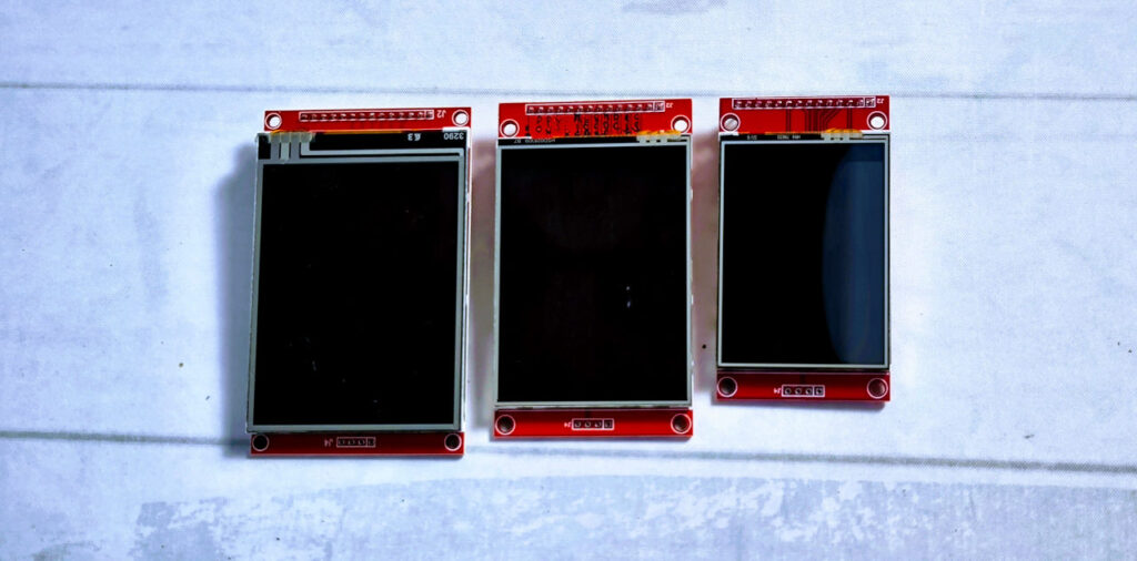
Here where to buy my selection of Display 240 * 320 ILI9341 2,8 - from 320 * 240 ILI9341 from 2,2 to 3,5 - TFT Round 240 * 240 GC9A01 1,28" - CrowPanel ESP32-C3 240*240 Round IPS Display Capacitive Touch 1,28" - Aliexpress CrowPanel ESP32-C3 240*240 Round IPS Display Capacitive Touch 1,28"- ESP32 2.8 Inch Touch ESP32-2432S028
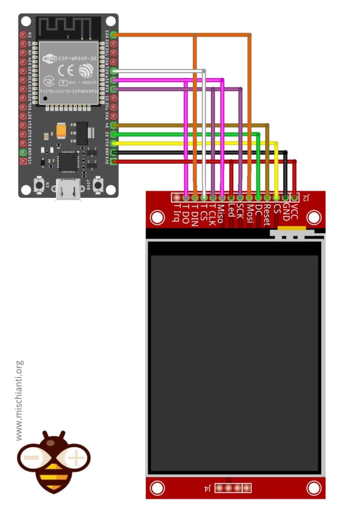
The ILI9341 uses SPI to communicate with the ESP32. Below is the standard wiring configuration:
| ILI9341 TFT Pin | ESP32 Pin | Description |
|---|---|---|
| VCC | 3.3V (With J1 soldered) or 5V | Power supply |
| GND | GND | Ground |
| CS | GPIO15 | Chip Select (TFT_CS) |
| RESET | GPIO4 | Display Reset |
| DC | GPIO2 | Data/Command (TFT_DC) |
| SDI (MOSI) | GPIO23 | SPI MOSI |
| SCK | GPIO18 | SPI Clock (SCLK) |
| SDO (MISO) | Not connected | Not required |
| LED | 3.3V | Backlight |
Note: If your ILI9341 module has a LED pin, connect it to 3.3V or a GPIO pin for backlight control.
Installing the TFT_eSPI Library
The TFT_eSPI Library isn’t just about blazing-fast graphics—it’s also designed to simplify touch integration on TFT displays with the ESP32 and similar microcontrollers. Built for high performance, the library not only supports a wide array of display drivers (including the ILI9143) but also streamlines the process of capturing and processing touch input.
A major advantage of TFT_eSPI is its user-friendly API, which allows developers to incorporate touch functionality into their projects without needing to get into the nitty-gritty of hardware-level details. With built-in functions for touch detection, calibration, and coordinate mapping, the library enables you to quickly add interactive features—such as virtual buttons, sliders, or keypads—to your display.
Furthermore, TFT_eSPI’s configuration options provide the flexibility to tailor both graphical output and touch sensitivity to your project’s specific needs. Whether you’re creating simple interfaces or complex, touch-driven applications, the library’s support for features like partial screen updates and multiple font types ensures that your touch-based user experience is both responsive and visually appealing.
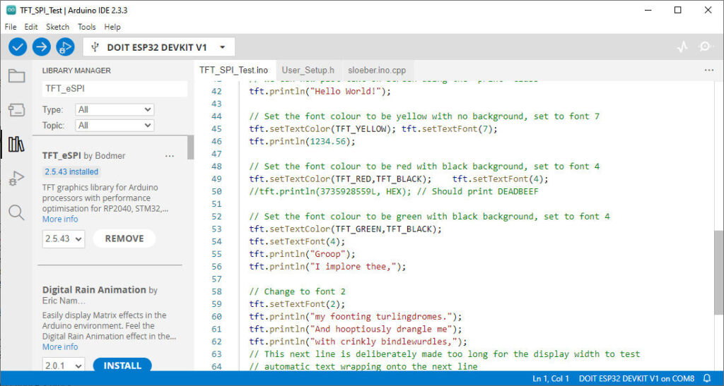
Open the Arduino IDE.
- Go to Tools > Manage Libraries.
- Search for
TFT_eSPIand install the library by Bodmer.
Library Configuration
This library isn’t ready to use. We must configure the microcontroller’s display and PINs correctly. To help with this, a file named UserSetupSelect.h exists under the main library folder. Here the default content.
// This header file contains a list of user setup files and defines which one the
// compiler uses when the IDE performs a Verify/Compile or Upload.
//
// Users can create configurations for different boards and TFT displays.
// This makes selecting between hardware setups easy by "uncommenting" one line.

// The advantage of this hardware configuration method is that the examples provided
// with the library should work with immediately without any other changes being
// needed. It also improves the portability of users sketches to other hardware
// configurations and compatible libraries.
//
// Create a shortcut to this file on your desktop to permit quick access for editing.
// Re-compile and upload after making and saving any changes to this file.

// Example User_Setup files are stored in the "User_Setups" folder. These can be used
// unmodified or adapted for a particular hardware configuration.

#ifndef USER_SETUP_LOADED //  Lets PlatformIO users define settings in
                          //  platformio.ini, see notes in "Tools" folder.

///////////////////////////////////////////////////////
//   User configuration selection lines are below    //
///////////////////////////////////////////////////////

// Only ONE line below should be uncommented to define your setup.  Add extra lines and files as needed.

#include <User_Setup.h>           // Default setup is root library folder

//#include <User_Setups/Setup1_ILI9341.h>  // Setup file for ESP8266 configured for my ILI9341
//#include <User_Setups/Setup2_ST7735.h>   // Setup file for ESP8266 configured for my ST7735
//#include <User_Setups/Setup3_ILI9163.h>  // Setup file for ESP8266 configured for my ILI9163
//#include <User_Setups/Setup4_S6D02A1.h>  // Setup file for ESP8266 configured for my S6D02A1
//#include <User_Setups/Setup5_RPi_ILI9486.h>        // Setup file for ESP8266 configured for my stock RPi TFT
//#include <User_Setups/Setup6_RPi_Wr_ILI9486.h>     // Setup file for ESP8266 configured for my modified RPi TFT
//#include <User_Setups/Setup7_ST7735_128x128.h>     // Setup file for ESP8266 configured for my ST7735 128x128 display
//#include <User_Setups/Setup8_ILI9163_128x128.h>    // Setup file for ESP8266 configured for my ILI9163 128x128 display
//#include <User_Setups/Setup9_ST7735_Overlap.h>     // Setup file for ESP8266 configured for my ST7735
//#include <User_Setups/Setup10_RPi_touch_ILI9486.h> // Setup file for ESP8266 configured for ESP8266 and RPi TFT with touch

//#include <User_Setups/Setup11_RPi_touch_ILI9486.h> // Setup file configured for ESP32 and RPi TFT with touch
//#include <User_Setups/Setup12_M5Stack_Basic_Core.h>// Setup file for the ESP32 based M5Stack (Basic Core only)
//#include <User_Setups/Setup13_ILI9481_Parallel.h>  // Setup file for the ESP32 with parallel bus TFT
//#include <User_Setups/Setup14_ILI9341_Parallel.h>  // Setup file for the ESP32 with parallel bus TFT
//#include <User_Setups/Setup15_HX8357D.h>           // Setup file for ESP8266 configured for HX8357D
//#include <User_Setups/Setup16_ILI9488_Parallel.h>  // Setup file for the ESP32 with parallel bus TFT
//#include <User_Setups/Setup17_ePaper.h>            // Setup file for ESP8266 and any Waveshare ePaper display
//#include <User_Setups/Setup18_ST7789.h>            // Setup file for ESP8266 configured for ST7789

//#include <User_Setups/Setup19_RM68140_Parallel.h>	 // Setup file configured for RM68140 with parallel bus

//#include <User_Setups/Setup20_ILI9488.h>           // Setup file for ESP8266 and ILI9488 SPI bus TFT
//#include <User_Setups/Setup21_ILI9488.h>           // Setup file for ESP32 and ILI9488 SPI bus TFT

//#include <User_Setups/Setup22_TTGO_T4.h>           // Setup file for ESP32 and TTGO T4 version 1.2
//#include <User_Setups/Setup22_TTGO_T4_v1.3.h>      // Setup file for ESP32 and TTGO T4 version 1.3
//#include <User_Setups/Setup23_TTGO_TM.h>           // Setup file for ESP32 and TTGO TM ST7789 SPI bus TFT
//#include <User_Setups/Setup24_ST7789.h>            // Setup file for DSTIKE/ESP32/ESP8266 configured for ST7789 240 x 240
//#include <User_Setups/Setup25_TTGO_T_Display.h>    // Setup file for ESP32 and TTGO T-Display ST7789V SPI bus TFT
//#include <User_Setups/Setup26_TTGO_T_Wristband.h>  // Setup file for ESP32 and TTGO T-Wristband ST7735 SPI bus TFT

//#include <User_Setups/Setup27_RPi_ST7796_ESP32.h>    // ESP32   RPi MHS-4.0 inch Display-B
//#include <User_Setups/Setup28_RPi_ST7796_ESP8266.h>  // ESP8266 RPi MHS-4.0 inch Display-B

//#include <User_Setups/Setup29_ILI9341_STM32.h>          // Setup for Nucleo board
//#include <User_Setups/Setup30_ILI9341_Parallel_STM32.h> // Setup for Nucleo board and parallel display
//#include <User_Setups/Setup31_ST7796_Parallel_STM32.h>  // Setup for Nucleo board and parallel display
//#include <User_Setups/Setup32_ILI9341_STM32F103.h>      // Setup for "Blue/Black Pill"

//#include <User_Setups/Setup33_RPi_ILI9486_STM32.h>      // Setup for Nucleo board

//#include <User_Setups/Setup34_ILI9481_Parallel_STM32.h> // Setup for Nucleo board and parallel display
//#include <User_Setups/Setup35_ILI9341_STM32_Port_Bus.h> // Setup for STM32 port A parallel display

//#include <User_Setups/Setup36_RPi_touch_ST7796.h>      // Setup file configured for ESP32 and RPi ST7796 TFT with touch

// #include <User_Setups/Setup42_ILI9341_ESP32.h>           // Setup file for ESP32 and SPI ILI9341 240x320
//#include <User_Setups/Setup43_ST7735.h>            // Setup file for ESP8266 & ESP32 configured for my ST7735S 80x160
//#include <User_Setups/Setup44_TTGO_CameraPlus.h>   // Setup file for ESP32 and TTGO T-CameraPlus ST7789 SPI bus TFT    240x240
//#include <User_Setups/Setup45_TTGO_T_Watch.h>      // Setup file for ESP32 and TTGO T-Watch ST7789 SPI bus TFT  240x240
//#include <User_Setups/Setup46_GC9A01_ESP32.h>      // Setup file for ESP32 and GC9A01 SPI bus TFT  240x240

//#include <User_Setups/Setup47_ST7735.h>            // Setup file for ESP32 configured for ST7735 128 x 128 animated eyes

//#include <User_Setups/Setup50_SSD1963_Parallel.h>  // Setup file for ESP32 and SSD1963 TFT display

//#include <User_Setups/Setup51_LilyPi_ILI9481.h>    // Setup file for LilyGo LilyPi with ILI9481 display
//#include <User_Setups/Setup52_LilyPi_ST7796.h>     // Setup file for LilyGo LilyPi with ST7796 display

//#include <User_Setups/Setup60_RP2040_ILI9341.h>              // Setup file for RP2040 with SPI ILI9341
//#include <User_Setups/Setup61_RP2040_ILI9341_PIO_SPI.h>      // Setup file for RP2040 with PIO SPI ILI9341
//#include <User_Setups/Setup62_RP2040_Nano_Connect_ILI9341.h> // Setup file for RP2040 with SPI ILI9341

//#include <User_Setups/Setup66_Seeed_XIAO_Round.h>     // Setup file for Seeed XIAO with GC9A01 240x240

//#include <User_Setups/Setup70_ESP32_S2_ILI9341.h>     // Setup file for ESP32 S2 with SPI ILI9341
//#include <User_Setups/Setup70b_ESP32_S3_ILI9341.h>    // Setup file for ESP32 S3 with SPI ILI9341
//#include <User_Setups/Setup70c_ESP32_C3_ILI9341.h>    // Setup file for ESP32 C3 with SPI ILI9341
//#include <User_Setups/Setup70d_ILI9488_S3_Parallel.h> // Setup file for ESP32 S3 with SPI ILI9488

//#include <User_Setups/Setup71_ESP32_S2_ST7789.h>       // Setup file for ESP32 S2 with ST7789
//#include <User_Setups/Setup72_ESP32_ST7789_172x320.h>  // Setup file for ESP32 with ST7789 1.47" 172x320

//#include <User_Setups/Setup100_RP2040_ILI9488_parallel.h> // Setup file for Pico/RP2040 with 8-bit parallel ILI9488
//#include <User_Setups/Setup101_RP2040_ILI9481_parallel.h> // Setup file for Pico/RP2040 with 8-bit parallel ILI9481
//#include <User_Setups/Setup102_RP2040_ILI9341_parallel.h> // Setup file for Pico/RP2040 with 8-bit parallel ILI9341
//#include <User_Setups/Setup103_RP2040_ILI9486_parallel.h> // Setup file for Pico/RP2040 with 8-bit parallel ILI9486
//#include <User_Setups/Setup104_RP2040_ST7796_parallel.h>  // Setup file for Pico/RP2040 with 8-bit parallel ST7796

//#include <User_Setups/Setup105_RP2040_ST7796_16bit_parallel.h>  // Setup file for RP2040 16-bit parallel display
//#include <User_Setups/Setup106_RP2040_ILI9481_16bit_parallel.h> // Setup file for RP2040 16-bit parallel display
//#include <User_Setups/Setup107_RP2040_ILI9341_16bit_parallel.h> // Setup file for RP2040 16-bit parallel display
//#include <User_Setups/Setup108_RP2040_ST7735.h> // Setup file for Waveshare RP2040 board with onboard ST7735 0.96" 160x80 display

//#include <User_Setups/Setup135_ST7789.h>           // Setup file for ESP8266 and ST7789 135 x 240 TFT

//#include <User_Setups/Setup136_LilyGo_TTV.h>       // Setup file for ESP32 and Lilygo TTV ST7789 SPI bus TFT  135x240
//#include <User_Setups/Setup137_LilyGo_TDisplay_RP2040.h>  // Setup file for Lilygo T-Display RP2040 (ST7789 on SPI bus with 135x240 TFT)

//#include <User_Setups/Setup138_Pico_Explorer_Base_RP2040_ST7789.h> // Setup file for Pico Explorer Base by Pimoroni for RP2040 (ST7789 on SPI bus with 240x240 TFT)

//#include <User_Setups/Setup200_GC9A01.h>           // Setup file for ESP32 and GC9A01 240 x 240 TFT

//#include <User_Setups/Setup201_WT32_SC01.h>        // Setup file for ESP32 based WT32_SC01 from Seeed

//#include <User_Setups/Setup202_SSD1351_128.h>      // Setup file for ESP32/ESP8266 based SSD1351 128x128 1.5inch OLED display

//#include <User_Setups/Setup203_ST7789.h>     // Setup file for ESP32/ESP8266 based ST7789 240X280 1.69inch TFT

//#include <User_Setups/Setup204_ESP32_TouchDown.h>     // Setup file for the ESP32 TouchDown based on ILI9488 480 x 320 TFT

//#include <User_Setups/Setup205_ESP32_TouchDown_S3.h>     // Setup file for the ESP32 TouchDown S3 based on ILI9488 480 x 320 TFT

//#include <User_Setups/Setup206_LilyGo_T_Display_S3.h>     // For the LilyGo T-Display S3 based ESP32S3 with ST7789 170 x 320 TFT
//#include <User_Setups/Setup207_LilyGo_T_HMI.h>            // For the LilyGo T-HMI S3 based ESP32S3 with ST7789 240 x 320 TFT
//#include <User_Setups/Setup209_LilyGo_T_Dongle_S3.h>      // For the LilyGo T-Dongle S3 based ESP32 with ST7735 80 x 160 TFT
//#include <User_Setups/Setup210_LilyGo_T_Embed_S3.h>         // For the LilyGo T-Embed S3 based ESP32S3 with ST7789 170 x 320 TFT
//#include <User_Setups/Setup211_LilyGo_T_QT_Pro_S3.h>         // For the LilyGo T-QT Pro S3 based ESP32S3 with GC9A01 128 x 128 TFT
// #include <User_Setups/Setup212_LilyGo_T_PicoPro.h>         // For the LilyGo T-PICO-Pro with ST7796 222 x 480 TFT
// #include <User_Setups/Setup213_LilyGo_T_Beam_Shield.h>         // For the LilyGo T-BEAM V1.x with ST7796 222 x 480 TFT

//#include <User_Setups/Setup250_ESP32_S3_Box_Lite.h>      // For the ESP32 S3 Box Lite
//#include <User_Setups/Setup251_ESP32_S3_Box.h>            // For the ESP32 S3 Box

//#include <User_Setups/Setup301_BW16_ST7735.h>            // Setup file for Bw16-based boards with ST7735 160 x 80 TFT
//#include <User_Setups/Setup302_Waveshare_ESP32S3_GC9A01.h>            // Setup file for Waveshare ESP32-S3-Touch-LCD-1.28 board with GC9A01 240*240 TFT

//#include <User_Setups/SetupX_Template.h>     // Template file for a setup


//#include <User_Setups/Dustin_ILI9488.h>          // Setup file for Dustin Watts PCB with ILI9488
//#include <User_Setups/Dustin_ST7796.h>           // Setup file for Dustin Watts PCB with ST7796
//#include <User_Setups/Dustin_ILI9488_Pico.h>     // Setup file for Dustin Watts Pico PCB with ST7796
//#include <User_Setups/Dustin_ST7789_Pico.h>      // Setup file for Dustin Watts PCB with ST7789 240 x 240 on 3.3V adapter board
//#include <User_Setups/Dustin_GC9A01_Pico.h>      // Setup file for Dustin Watts PCB with GC9A01 240 x 240 on 3.3V adapter board
//#include <User_Setups/Dustin_GC9A01_ESP32.h>     // Setup file for Dustin Watts PCB with GC9A01 240 x 240 on 3.3V adapter board
//#include <User_Setups/Dustin_STT7789_ESP32.h>    // Setup file for Dustin Watts PCB with ST7789 240 x 240 on 3.3V adapter board
//#include <User_Setups/Dustin_ILI9341_ESP32.h>    // Setup file for Dustin Watts PCB with ILI9341
//#include <User_Setups/ILI9225.h>

#endif // USER_SETUP_LOADED


/////////////////////////////////////////////////////////////////////////////////////
//                                                                                 //
//     DON'T TINKER WITH ANY OF THE FOLLOWING LINES, THESE ADD THE TFT DRIVERS     //
//       AND ESP8266 PIN DEFINITONS, THEY ARE HERE FOR BODMER'S CONVENIENCE!       //
//                                                                                 //
/////////////////////////////////////////////////////////////////////////////////////


// Identical looking TFT displays may have a different colour ordering in the 16-bit colour
#define TFT_BGR 0   // Colour order Blue-Green-Red
#define TFT_RGB 1   // Colour order Red-Green-Blue

// Legacy setup support, RPI_DISPLAY_TYPE replaces RPI_DRIVER
#if defined (RPI_DRIVER)
  #if !defined (RPI_DISPLAY_TYPE)
    #define RPI_DISPLAY_TYPE
  #endif
#endif

// Legacy setup support, RPI_ILI9486_DRIVER form is deprecated
// Instead define RPI_DISPLAY_TYPE and also define driver (e.g. ILI9486_DRIVER)
#if defined (RPI_ILI9486_DRIVER)
  #if !defined (ILI9486_DRIVER)
    #define ILI9486_DRIVER
  #endif
  #if !defined (RPI_DISPLAY_TYPE)
    #define RPI_DISPLAY_TYPE
  #endif
#endif

// Invoke 18-bit colour for selected displays
#if !defined (RPI_DISPLAY_TYPE) && !defined (TFT_PARALLEL_8_BIT) && !defined (TFT_PARALLEL_16_BIT) && !defined (ESP32_PARALLEL)
  #if defined (ILI9481_DRIVER) || defined (ILI9486_DRIVER) || defined (ILI9488_DRIVER)
    #define SPI_18BIT_DRIVER
  #endif
#endif

// Load the right driver definition - do not tinker here !
#if   defined (ILI9341_DRIVER) || defined(ILI9341_2_DRIVER) || defined (ILI9342_DRIVER)
     #include <TFT_Drivers/ILI9341_Defines.h>
     #define  TFT_DRIVER 0x9341
#elif defined (ST7735_DRIVER)
     #include <TFT_Drivers/ST7735_Defines.h>
     #define  TFT_DRIVER 0x7735
#elif defined (ILI9163_DRIVER)
     #include <TFT_Drivers/ILI9163_Defines.h>
     #define  TFT_DRIVER 0x9163
#elif defined (S6D02A1_DRIVER)
     #include <TFT_Drivers/S6D02A1_Defines.h>
     #define  TFT_DRIVER 0x6D02
#elif defined (ST7796_DRIVER)
      #include "TFT_Drivers/ST7796_Defines.h"
      #define  TFT_DRIVER 0x7796
#elif defined (ILI9486_DRIVER)
     #include <TFT_Drivers/ILI9486_Defines.h>
     #define  TFT_DRIVER 0x9486
#elif defined (ILI9481_DRIVER)
     #include <TFT_Drivers/ILI9481_Defines.h>
     #define  TFT_DRIVER 0x9481
#elif defined (ILI9488_DRIVER)
     #include <TFT_Drivers/ILI9488_Defines.h>
     #define  TFT_DRIVER 0x9488
#elif defined (HX8357D_DRIVER)
     #include "TFT_Drivers/HX8357D_Defines.h"
     #define  TFT_DRIVER 0x8357
#elif defined (EPD_DRIVER)
     #include "TFT_Drivers/EPD_Defines.h"
     #define  TFT_DRIVER 0xE9D
#elif defined (ST7789_DRIVER)
     #include "TFT_Drivers/ST7789_Defines.h"
     #define  TFT_DRIVER 0x7789
#elif defined (R61581_DRIVER)
     #include "TFT_Drivers/R61581_Defines.h"
     #define  TFT_DRIVER 0x6158
#elif defined (ST7789_2_DRIVER)
     #include "TFT_Drivers/ST7789_2_Defines.h"
     #define  TFT_DRIVER 0x778B
#elif defined (RM68140_DRIVER)
     #include "TFT_Drivers/RM68140_Defines.h"
     #define  TFT_DRIVER 0x6814
#elif defined (SSD1351_DRIVER)
     #include "TFT_Drivers/SSD1351_Defines.h"
     #define  TFT_DRIVER 0x1351
#elif defined (SSD1963_480_DRIVER)
     #include "TFT_Drivers/SSD1963_Defines.h"
     #define  TFT_DRIVER 0x1963
#elif defined (SSD1963_800_DRIVER)
     #include "TFT_Drivers/SSD1963_Defines.h"
     #define  TFT_DRIVER 0x1963
#elif defined (SSD1963_800ALT_DRIVER)
     #include "TFT_Drivers/SSD1963_Defines.h"
     #define  TFT_DRIVER 0x1963
#elif defined (SSD1963_800BD_DRIVER)
     #include "TFT_Drivers/SSD1963_Defines.h"
     #define  TFT_DRIVER 0x1963
#elif defined (GC9A01_DRIVER)
     #include "TFT_Drivers/GC9A01_Defines.h"
     #define  TFT_DRIVER 0x9A01
#elif defined (ILI9225_DRIVER)
     #include "TFT_Drivers/ILI9225_Defines.h"
     #define  TFT_DRIVER 0x9225
#elif defined (RM68120_DRIVER)
     #include "TFT_Drivers/RM68120_Defines.h"
     #define  TFT_DRIVER 0x6812
#elif defined (HX8357B_DRIVER)
     #include "TFT_Drivers/HX8357B_Defines.h"
     #define  TFT_DRIVER 0x835B
#elif defined (HX8357C_DRIVER)
     #include "TFT_Drivers/HX8357C_Defines.h"
     #define  TFT_DRIVER 0x835C

                              // <<<<<<<<<<<<<<<<<<<<<<<< ADD NEW DRIVER HERE
                              // XYZZY_init.h and XYZZY_rotation.h must also be added in TFT_eSPI.cpp
#elif defined (XYZZY_DRIVER)
     #include "TFT_Drivers/XYZZY_Defines.h"
     #define  TFT_DRIVER 0x0000
#else
     #define  TFT_DRIVER 0x0000
#endif

// These are the pins for ESP8266 boards
//      Name   GPIO    NodeMCU      Function
#define PIN_D0  16  // GPIO16       WAKE
#define PIN_D1   5  // GPIO5        User purpose
#define PIN_D2   4  // GPIO4        User purpose
#define PIN_D3   0  // GPIO0        Low on boot means enter FLASH mode
#define PIN_D4   2  // GPIO2        TXD1 (must be high on boot to go to UART0 FLASH mode)
#define PIN_D5  14  // GPIO14       HSCLK
#define PIN_D6  12  // GPIO12       HMISO
#define PIN_D7  13  // GPIO13       HMOSI  RXD2
#define PIN_D8  15  // GPIO15       HCS    TXD0 (must be low on boot to enter UART0 FLASH mode)
#define PIN_D9   3  //              RXD0
#define PIN_D10  1  //              TXD0

#define PIN_MOSI 8  // SD1          FLASH and overlap mode
#define PIN_MISO 7  // SD0
#define PIN_SCLK 6  // CLK
#define PIN_HWCS 0  // D3

#define PIN_D11  9  // SD2
#define PIN_D12 10  // SD4
This configuration file is enabled by default, and by default, the file User_Setup.h is uncommented and selected. But you can see a commented line with this text
#include <User_Setups/Setup42_ILI9341_ESP32.h> // Setup file for ESP32 and SPI ILI9341 240x320
Inside that file there is a basic configuration for our display.
// See SetupX_Template.h for all options available
#define USER_SETUP_ID 42

#define ILI9341_DRIVER

#define TFT_MISO 19  // (leave TFT SDO disconnected if other SPI devices share MISO)
#define TFT_MOSI 23
#define TFT_SCLK 18
#define TFT_CS   15  // Chip select control pin
#define TFT_DC    2  // Data Command control pin
#define TFT_RST   4  // Reset pin (could connect to RST pin)

// Optional touch screen chip select
#define TOUCH_CS 21 // Chip select pin (T_CS) of touch screen

#define LOAD_GLCD    // Font 1. Original Adafruit 8 pixel font needs ~1820 bytes in FLASH
#define LOAD_FONT2   // Font 2. Small 16 pixel high font, needs ~3534 bytes in FLASH, 96 characters
#define LOAD_FONT4   // Font 4. Medium 26 pixel high font, needs ~5848 bytes in FLASH, 96 characters
#define LOAD_FONT6   // Font 6. Large 48 pixel font, needs ~2666 bytes in FLASH, only characters 1234567890:-.apm
#define LOAD_FONT7   // Font 7. 7 segment 48 pixel font, needs ~2438 bytes in FLASH, only characters 1234567890:.
#define LOAD_FONT8   // Font 8. Large 75 pixel font needs ~3256 bytes in FLASH, only characters 1234567890:-.
#define LOAD_GFXFF   // FreeFonts. Include access to the 48 Adafruit_GFX free fonts FF1 to FF48 and custom fonts

#define SMOOTH_FONT

// TFT SPI clock frequency
// #define SPI_FREQUENCY  20000000
// #define SPI_FREQUENCY  27000000
#define SPI_FREQUENCY  40000000
// #define SPI_FREQUENCY  80000000

// Optional reduced SPI frequency for reading TFT
#define SPI_READ_FREQUENCY  16000000

// SPI clock frequency for touch controller
#define SPI_TOUCH_FREQUENCY  2500000
This configuration is pretty good, but I prefer to set a specified file inside the project folder without change the library files because on update you lost all the change you made.
So we can disable the content of the default configuration by adding a defined USER_SETUP, and I created a custom file User_Setup.h in the folder of my project.
// Add this in the header of the project file
#define USER_SETUP_LOADED //for not loading internal USER_SETTINGS

#include "User_Setup.h"
Our custom User_Setup.h become like so.
/**
 * User setup for ili9143 and esp32
 * by Renzo Mischianti <mischianti.org>
 * Tutorial for ili9143
 */

#define USER_SETUP_INFO "User_Setup"

// ##################################################################################
//
// Section 1. Call up the right driver file and any options for it
//
// ##################################################################################

#define ILI9341_DRIVER       // Generic driver for common displays

#define TFT_WIDTH  240 // ST7789 240 x 240 and 240 x 320
#define TFT_HEIGHT 320 // ST7789 240 x 320


// ##################################################################################
//
// Section 2. Define the pins that are used to interface with the display here
//
// ##################################################################################

// If a backlight control signal is available then define the TFT_BL pin in Section 2
// below. The backlight will be turned ON when tft.begin() is called, but the library
// needs to know if the LEDs are ON with the pin HIGH or LOW. If the LEDs are to be
// driven with a PWM signal or turned OFF/ON then this must be handled by the user
// sketch. e.g. with digitalWrite(TFT_BL, LOW);

// ###### EDIT THE PIN NUMBERS IN THE LINES FOLLOWING TO SUIT YOUR ESP32 SETUP   ######

// For ESP32 Dev board (only tested with ILI9341 display)
// The hardware SPI can be mapped to any pins

#define TFT_MISO 19
#define TFT_MOSI 23
#define TFT_SCLK 18
#define TFT_CS   15  // Chip select control pin
#define TFT_DC    2  // Data Command control pin
#define TFT_RST   4  // Reset pin (could connect to RST pin)

//#define TFT_RST  -1  // Set TFT_RST to -1 if display RESET is connected to ESP32 board RST
//#define TFT_BL   22  // LED back-light

#define TOUCH_CS 21     // Chip select pin (T_CS) of touch screen

// ##################################################################################
//
// Section 3. Define the fonts that are to be used here
//
// ##################################################################################

// Comment out the #defines below with // to stop that font being loaded
// The ESP8366 and ESP32 have plenty of memory so commenting out fonts is not
// normally necessary. If all fonts are loaded the extra FLASH space required is
// about 17Kbytes. To save FLASH space only enable the fonts you need!

#define LOAD_GLCD   // Font 1. Original Adafruit 8 pixel font needs ~1820 bytes in FLASH
#define LOAD_FONT2  // Font 2. Small 16 pixel high font, needs ~3534 bytes in FLASH, 96 characters
#define LOAD_FONT4  // Font 4. Medium 26 pixel high font, needs ~5848 bytes in FLASH, 96 characters
#define LOAD_FONT6  // Font 6. Large 48 pixel font, needs ~2666 bytes in FLASH, only characters 1234567890:-.apm
#define LOAD_FONT7  // Font 7. 7 segment 48 pixel font, needs ~2438 bytes in FLASH, only characters 1234567890:-.
#define LOAD_FONT8  // Font 8. Large 75 pixel font needs ~3256 bytes in FLASH, only characters 1234567890:-.
//#define LOAD_FONT8N // Font 8. Alternative to Font 8 above, slightly narrower, so 3 digits fit a 160 pixel TFT
#define LOAD_GFXFF  // FreeFonts. Include access to the 48 Adafruit_GFX free fonts FF1 to FF48 and custom fonts

// Comment out the #define below to stop the SPIFFS filing system and smooth font code being loaded
// this will save ~20kbytes of FLASH
#define SMOOTH_FONT

// ##################################################################################
//
// Section 4. Other options
//
// ##################################################################################

// TFT SPI clock frequency
// #define SPI_FREQUENCY  20000000
// #define SPI_FREQUENCY  27000000
#define SPI_FREQUENCY  40000000
// #define SPI_FREQUENCY  80000000

// Optional reduced SPI frequency for reading TFT
#define SPI_READ_FREQUENCY  16000000

// SPI clock frequency for touch controller
#define SPI_TOUCH_FREQUENCY  2500000
//#define SPI_TOUCH_FREQUENCY 1000000 // Reduce to 1 MHz for debugging

// Transactions are automatically enabled by the library for an ESP32 (to use HAL mutex)
// so changing it here has no effect

// #define SUPPORT_TRANSACTIONS
Introducing the XPT2046_Touchscreen Library
While the TFT_eSPI library provides built‐in support for basic touch functionality, the XPT2046_Touchscreen library is a dedicated solution for displays equipped with the XPT2046 touch controller. This library is specifically optimized for resistive touchscreens based on the XPT2046 chip, offering enhanced calibration routines, better noise filtering, and more detailed touch event handling than what you might get from a general-purpose solution.
When to Use XPT2046_Touchscreen:
- Hardware Specificity: If your TFT module incorporates the XPT2046 controller, this library is tailored to work optimally with that chip.
- Advanced Touch Handling: For projects that require refined touch inputs—such as improved calibration, gesture recognition, or pressure sensitivity—the XPT2046_Touchscreen library provides additional functionality beyond the basic support offered by TFT_eSPI.
- Code Modularity: Separating display control (handled by TFT_eSPI) from touch management (handled by XPT2046_Touchscreen) can help maintain a cleaner, more modular codebase.
Basic Sketch Example Using XPT2046_Touchscreen
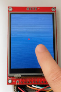
Below is a simple sketch that demonstrates how to initialize and use the XPT2046_Touchscreen library alongside TFT_eSPI. In this example, when you touch the screen, a small red circle will be drawn at the touch location, and the coordinates will be printed to the Serial Monitor.
/*
  Basic Touch Drawing Example Using XPT2046_Touchscreen
  and TFT_eSPI (shared SPI bus)

  Created by Renzo Mischianti
  www.mischianti.org
*/

#include <TFT_eSPI.h>
#include <XPT2046_Touchscreen.h>
#include <SPI.h>

// TFT_eSPI uses the default SPI bus
TFT_eSPI tft = TFT_eSPI();  // TFT driver

#define TOUCH_CS 21
#define TOUCH_IRQ 255  // Not used, set to -1 or 255 if unused

XPT2046_Touchscreen ts(TOUCH_CS, TOUCH_IRQ);

// Calibration range (adjust if needed)
uint16_t touchScreenMinimumX = 200, touchScreenMaximumX = 3700;
uint16_t touchScreenMinimumY = 240, touchScreenMaximumY = 3800;

void setup() {
  Serial.begin(115200);

  tft.init();
  tft.setRotation(0);        // Match your setup
  tft.fillScreen(TFT_BLACK);

  ts.begin();                // Init touchscreen
  ts.setRotation(1);         // May vary depending on your wiring

  Serial.println("Touch test with XPT2046 ready.");
}

void loop() {
  if (ts.touched()) {
    TS_Point p = ts.getPoint();

    // Auto-calibrate (basic min/max tracker)
    if (p.x < touchScreenMinimumX) touchScreenMinimumX = p.x;
    if (p.x > touchScreenMaximumX) touchScreenMaximumX = p.x;
    if (p.y < touchScreenMinimumY) touchScreenMinimumY = p.y;
    if (p.y > touchScreenMaximumY) touchScreenMaximumY = p.y;

    // Map to display coordinates
    uint16_t x = map(p.x, touchScreenMinimumX, touchScreenMaximumX, 0, tft.width());
    uint16_t y = map(p.y, touchScreenMinimumY, touchScreenMaximumY, 0, tft.height());

    tft.fillCircle(x, y, 5, TFT_RED);  // Draw red dot

    Serial.print("Touch at: ");
    Serial.print(x);
    Serial.print(", ");
    Serial.println(y);

    delay(100);  // debounce
  }
}
Explanation:
- Initialization:
The sketch begins by initializing both the TFT display (using TFT_eSPI) and the touchscreen (using XPT2046_Touchscreen). - Calibration Mapping:
The raw values from the touchscreen (p.x and p.y) are mapped to the pixel dimensions of the display using preset calibration constants. These constants should be adjusted for your specific setup. - Touch Response:
When a touch is detected, the code draws a small red circle at the corresponding screen coordinates and outputs these coordinates via Serial.
This example illustrates the basic integration of the XPT2046_Touchscreen library, which you can further expand upon for more complex touch-based interfaces.
Introduction to TFT_eSPI Touch Support
The TFT_eSPI library isn’t just about high-speed graphics—it also provides an integrated solution for touch functionality on TFT displays. If your display module includes a touchscreen (typically resistive), you can leverage the library’s built-in touch support without needing an external touch-specific library. This integration is controlled in part by the TOUCH_CS parameter, which designates the Chip Select (CS) pin for the touch controller.
The Role of TOUCH_CS
In many TFT display modules with a touchscreen, the touch controller communicates over SPI. To enable the TFT_eSPI library to handle touch input, you must define the pin that the touchscreen’s CS is connected to. For example, if your touchscreen’s CS line is connected to GPIO 21 on an ESP32, you would set the following in your configuration (usually in the User_Setup.h file):
#define TOUCH_CS 21 // Chip Select for touch controller
This definition allows the library to correctly initialize and communicate with the touchscreen hardware. Adjust this value according to your wiring.
Overall, whether you’re a beginner exploring interactive displays or an experienced developer looking to build sophisticated touch-driven applications, the TFT_eSPI library with its built-in touch support offers a flexible and efficient solution.
Below is a very basic example using the built‐in touch support of the TFT_eSPI library. This sketch will initialize the display, detect a touch, draw a small red circle at the touch location, and print the coordinates to the Serial Monitor.
/*
  Basic Example Using TFT_eSPI Touch

  Created by Renzo Mischianti
  www.mischianti.org

  This sketch initializes the TFT display and uses the built-in
  touch support provided by the TFT_eSPI library to detect touch events.
  When a touch is detected, a small red circle is drawn at the touch location,
  and the coordinates are printed to the Serial Monitor.

  Make sure you have defined the TOUCH_CS pin in your User_Setup.h file, e.g.,
  #define TOUCH_CS 21
*/

#include <TFT_eSPI.h>
#include <SPI.h>

// Create TFT display instance
TFT_eSPI tft = TFT_eSPI();

void setup() {
  Serial.begin(115200);
  tft.init();
  tft.fillScreen(TFT_BLACK);
  tft.setRotation(0);  // Adjust rotation if necessary
}

void loop() {
  uint16_t x, y;
  // getTouch() returns true if a valid touch is detected and assigns coordinates to x and y.
  if (tft.getTouch(&x, &y)) {
    // Draw a small red circle at the touched position
    tft.fillCircle(x, y, 5, TFT_RED);

    // Print the touch coordinates to the Serial Monitor
    Serial.print("Touch at: ");
    Serial.print(x);
    Serial.print(", ");
    Serial.println(y);

    delay(100);  // Simple debouncing delay
  }
}
This example demonstrates a simple way to incorporate touch interactivity using only the TFT_eSPI library. It’s perfect for quick projects, prototypes, and educational applications where ease of use and minimal setup are key.
Serial output:
Touch at: 75, 120
Touch at: 80, 115
Touch at: 120, 100
Thanks
- ESP32: pinout, specs and Arduino IDE configuration
- ESP32: integrated SPIFFS Filesystem
- ESP32: manage multiple Serial and logging
- ESP32 practical power saving
- ESP32 practical power saving: manage WiFi and CPU
- ESP32 practical power saving: modem and light sleep
- ESP32 practical power saving: deep sleep and hibernation
- ESP32 practical power saving: preserve data, timer and touch wake up
- ESP32 practical power saving: external and ULP wake up
- ESP32 practical power saving: UART and GPIO wake up
- ESP32: integrated LittleFS FileSystem
- ESP32: integrated FFat (Fat/exFAT) FileSystem
- ESP32-wroom-32
- ESP32-CAM
- ESP32: use ethernet w5500 with plain (HTTP) and SSL (HTTPS)
- ESP32: use ethernet enc28j60 with plain (HTTP) and SSL (HTTPS)
- How to use SD card with esp32
- esp32 and esp8266: FAT filesystem on external SPI flash memory
- Firmware and OTA update management
- Firmware management
- OTA update with Arduino IDE
- OTA update with Web Browser
- Self OTA uptate from HTTP server
- Non-standard Firmware update
- Integrating LAN8720 with ESP32 for Ethernet Connectivity with plain (HTTP) and SSL (HTTPS)
- Connecting the EByte E70 to ESP32 c3/s3 devices and a simple sketch example
- ESP32-C3: pinout, specs and Arduino IDE configuration
- Integrating W5500 with ESP32 Using Core 3: Native Ethernet Protocol Support with SSL and Other Features
- Integrating LAN8720 with ESP32 Using Core 3: Native Ethernet Protocol Support with SSL and Other Features
- Dallas ds18b20:
- Guide to I2C on ESP32: Communication with Heterogeneous 5V and 3.3V Devices, Additional Interface Management and Scanner
- Display
- Complete Guide: Using an ILI9341 Display with the TFT_eSPI Library
- Integrating Touch Screen Functionality with Your ILI9341 TFT Display
- SSD1683 eInk Display with GxEPD and ESP32 (and CrowPanel 4.2″ HMI): basics and configuration
- SSD1683 eInk Display with GxEPD and ESP32 (and CrowPanel 4.2″ HMI): fonts, shapes, and images
- ESP32 e Display eInk SSD1683: come realizzare una Semplice Stazione Meteo (anche su CrowPanel 4.2″ HMI) con le API di OpenWeatherMap
- How to Send Emails with Attachments on ESP32/ESP8266 (EMailSender v4.0.0 & STARTTLS)
- ESP32 High Performance FTP Server: A Deep Dive into the MultiFTPServer Library (v3.x)
- Ultra WideBand (Positioning system)
- Reyax RYUW122_Lite (UWB): Pinout, Datasheet, Schema & Specs
- Precision Indoor Positioning (cm) with UWB, ESP32 & Arduino: Hardware & Basics
- UWB Indoor Positioning: Standard Architecture (Anchor & Tag) with RYUW122
- Standalone UWB Positioning: The “IPS” Reverse Architecture (GPS-like) with RYUW122
- HC-SR04 Ultrasonic Sensor with ESP32 and Arduino: Complete Guide
- How to connect multiple HC-SR04 sensors with PCF8574 (3 methods)
- Fix slow HC-SR04 sensors with PCF8574: the hybrid approach trick [Guide]
- Complete Guide: Using an ILI9341 Display with the TFT_eSPI Library
- Integrating Touch Screen Functionality with Your ILI9341 TFT Display
- SSD1683 eInk Display with GxEPD and ESP32 (and CrowPanel 4.2″ HMI): basics and configuration
- SSD1683 eInk Display with GxEPD and ESP32 (and CrowPanel 4.2″ HMI): fonts, shapes, and images
- ESP32 e Display eInk SSD1683: come realizzare una Semplice Stazione Meteo (anche su CrowPanel 4.2″ HMI) con le API di OpenWeatherMap


Hi
i have tried 6 different IL9341
Using EXACTLY the same schematic connections and same identical file setting.
I see everything in the display but touch doe snot works.
Impossible
I am desperate and i do not know what to do anymore.
Can someone help me ?
Monitor always show :
Hi Leonard,
I made a mistake on the wiring schema; please recheck it.
The two touch pins (T DIN <-> T DO) were inverted. Please make sure to clear your browser cache so you can see the updated image.
Sorry Renzo