Guide to I2C on ESP32: Communication with Heterogeneous 5V and 3.3V Devices, Additional Interface Management and Scanner
I love the I2C protocol, when I need a sensor, every time, I try to find one with this protocol, I have also written some libraries for various sensors that use I2C. So I want to write some articles explaining (Arduino, Arduino SAMD MKR, esp8266 and esp32) some interesting features and I will try to explain how to solve the problems you can have when working with multiple I2C devices.
esp32 It’s a good compromise of price and power, It has a lot of features and connectivity features.
Introduction to I2C protocol
I2C (Inter-Integrated Circuit, eye-squared-C) and is alternatively known as I2C or IIC. It is a synchronous, multi-master, multi-slave, packet switched, single-ended, serial communication bus. Invented in 1982 by Philips Semiconductors. It is widely used for attaching lower-speed peripheral ICs to processors and microcontrollers in short-distance, intra-board communication. (cit. WiKi)
Speed
I2C supports 100 kbps, 400 kbps, 3.4 Mbps. Some variants also supports 10 Kbps and 1 Mbps.
| Mode | Maximum speed | Maximum capacitance | Drive | Direction |
|---|---|---|---|---|
| Standard-mode (Sm) | 100 kbit/s | 400 pF | Open drain | Bidirectional |
| Fast-mode (Fm) | 400 kbit/s | 400 pF | Open drain | Bidirectional |
| Fast-mode Plus (Fm+) | 1 Mbit/s | 550 pF | Open drain | Bidirectional |
| High-speed mode (Hs) | 1.7 Mbit/s | 400 pF | Open drain | Bidirectional |
| High-speed mode (Hs) | 3.4 Mbit/s | 100 pF | Open drain | Bidirectional |
| Ultra Fast-mode (UFm) | 5 Mbit/s | Push-pull | Unidirectional |
Interface
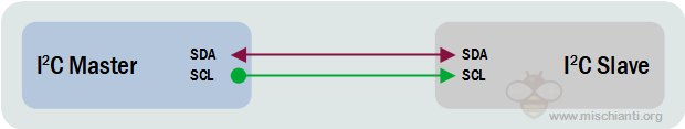
Like UART communication, I2C only uses two wires to transmit data between devices:
- SDA (Serial Data) – The line for the master and slave to send and receive data.
- SCL (Serial Clock) – The line that carries the clock signal (common clock signal between multiple masters and multiple slaves).
I2C is a serial communication protocol, so data is transferred bit by bit along a single wire (the SDA line).
Like SPI, I2C is synchronous, so the output of bits is synchronized to the sampling of bits by a clock signal shared between the master and the slave. The clock signal is always controlled by the master.
There will be multiple slaves and multiple masters and all masters can communicate with all the slaves.

- Start: The SDA line switches from a high voltage level to a low voltage level before the SCL line switches from high to low.
- Stop: The SDA line switches from a low voltage level to a high voltage level after the SCL line switches from low to high.
- Address Frame: A 7 or 10 bit sequence unique to each slave that identifies the slave when the master wants to talk to it.
- Read/Write Bit: A single bit specifying whether the master is sending data to the slave (low voltage level) or requesting data from it (high voltage level).
- ACK/NACK Bit: Each frame in a message is followed by an acknowledge/no-acknowledge bit. If an address frame or data frame was successfully received, an ACK bit is returned to the sender from the receiving device.
Devices connections
Because I2C uses addressing, multiple slaves can be controlled from a single master. With a 7 bit address, 128 (27) unique address are available. Using 10 bit addresses is uncommon, but provides 1,024 (210) unique addresses. Upto 27 slave devices can be connected/addressed in the I2C interface circuit.
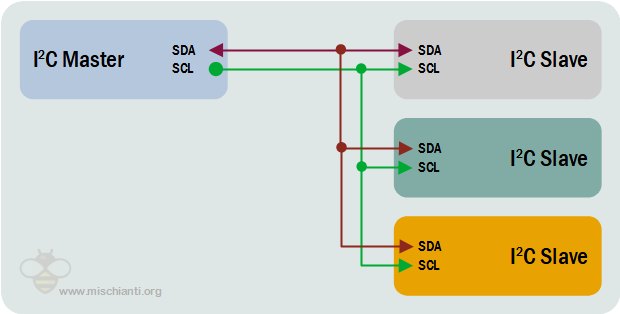
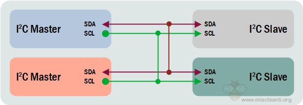
Multiple masters can be connected to a single slave or multiple slaves. The problem with multiple masters in the same system comes when two masters try to send or receive data at the same time over the SDA line. To solve this problem, each master needs to detect if the SDA line is low or high before transmitting a message. If the SDA line is low, this means that another master has control of the bus, and the master should wait to send the message. If the SDA line is high, then it’s safe to transmit the message. To connect multiple masters to multiple slaves
ESP32 and I2C
The ESP32 supports I2C communication through its two I2C bus interfaces I use them always as master because slave mode in Arduino IDE is not jet supported and there are a lot of problems about that.
- Standard mode (100 Kbit/s)
- Fast mode (400 Kbit/s)
- Up to 5 MHz, yet constrained by SDA pull-up strength
- 7-bit/10-bit addressing mode
- Dual addressing mode. Users can program command registers to control I²C interfaces, so that they have more flexibility
ESP32 as slave
Right now, the I2C Slave functionality is not implemented in ESP32 Arduino Core (see issue #118).
The ESP IDF, on the other hand, provides only two functions for the ESP32 to communicate as a slave device, and although it says a custom ISR function can be defined, there’s no example on how to do it properly (like reading and clearing interrupt flags).
There is a non standard workaround to permit to ESP32 to work as slave, and you can find here on GitHub the library developed for this purpose, but we don’t analyze that in this article.
I2C address scanner
I add this sketch now so you can test the connection fast.
#include <Wire.h>

void setup()
{
  Wire.begin();

  Serial.begin(9600);
  Serial.println("\nI2C Scanner");
}


void loop()
{
  byte error, address;
  int nDevices;

  Serial.println("Scanning...");

  nDevices = 0;
  for(address = 1; address < 127; address++ )
  {
    // The i2c_scanner uses the return value of
    // the Write.endTransmisstion to see if
    // a device did acknowledge to the address.
    Wire.beginTransmission(address);
    error = Wire.endTransmission();

    if (error == 0)
    {
      Serial.print("I2C device found at address 0x");
      if (address<16)
        Serial.print("0");
      Serial.print(address,HEX);
      Serial.println("  !");

      nDevices++;
    }
    else if (error==4)
    {
      Serial.print("Unknow error at address 0x");
      if (address<16)
        Serial.print("0");
      Serial.println(address,HEX);
    }
  }
  if (nDevices == 0)
    Serial.println("No I2C devices found\n");
  else
    Serial.println("done\n");

  delay(5000);           // wait 5 seconds for next scan
}
ESP32 as master basic use
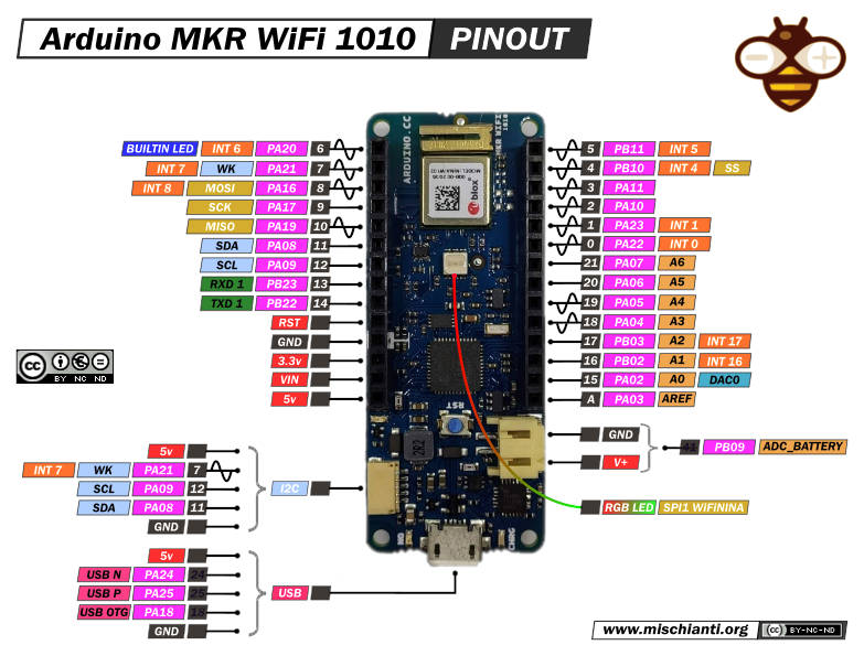
You can buy my Arduino SAMD here Arduino MKR WiFi 1010
For this test I use an Arduino MKR 1010 WiFi as slave, to get more information read “i2c Arduino SAMD MKR: additional interface SERCOM, network and address scanner”.
Sketchs are the same of the previous article, the Master start i2c interface, with the default i2c pins
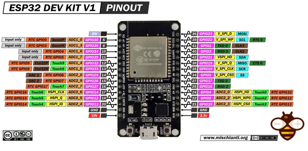
You can buy the esp32 from my selection here ESP32 Dev Kit v1 - TTGO T-Display 1.14 ESP32 - NodeMCU V3 V2 ESP8266 Lolin32 - NodeMCU ESP-32S - WeMos Lolin32 - WeMos Lolin32 mini - ESP32-CAM programmer - ESP32-CAM bundle - ESP32-WROOM-32 - ESP32-S - ESP32-WROOM-32 - ESP32 2.8 Inch Touch ESP32-2432S028
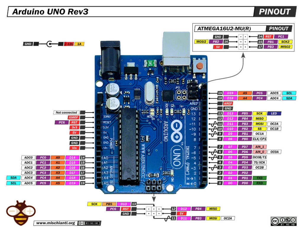
you can see in the pinout image 22 and 21 are the default SCL and SDA pin, so you must only call
Wire.begin(); // join i2c bus (address optional for master)
then send a request to the slave
	Wire.beginTransmission(0x10); 	// Start channel with slave 0x10
	Wire.write(GET_NAME);        		// send data to the slave
	Wire.endTransmission();       	// End transmission
where 0x10 is the address of the slave, the slave initialize I2C with the same address
Wire.begin(0x10); // join i2c bus with address 0x10
and wait for requests and data
	// event handler initializations
	Wire.onReceive(receiveEvent);    // register an event handler for received data
	Wire.onRequest(requestEvent);   // register an event handler for data requests
in this case receive data is called and you can get the data sended
// function that executes whenever data is received by master
// this function is registered as an event, see setup()
void receiveEvent(int numBytes) {
	if (numBytes==1){
		int requestVal = Wire.read();

		Serial.print(F("Received request -> "));
		Serial.println(requestVal);
		request = static_cast<I2C_REQUEST_TYPE>(requestVal);
	}else{
		Serial.print(F("No parameter received!"));
	}
}
when the data is received the Master open a request
	Wire.requestFrom(0x10, 14);    // request 14 bytes from slave device 0x10

	while (Wire.available()) { // slave may send less than requested
	      char c = Wire.read(); // receive a byte as character
	      Serial.print(c);         // print the character
	}
with Wire.requestFrom(0x10, 14); ask to address 0x10 14bytes of data, and check if data are in the buffer, if data available read them.
Here the complete Master sketch for ESP32.
/**
* i2c network: send parameter to client and receive response
* with data relative to the request
*
* by Renzo Mischianti <www.mischianti.org>
*
* https://mischianti.org
*
*
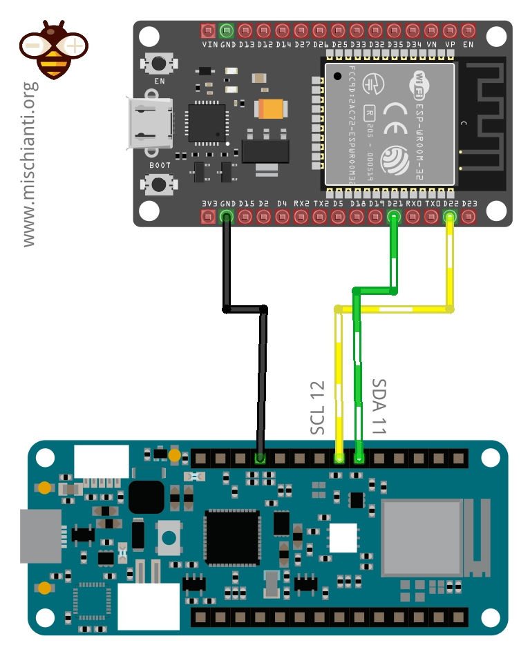
* ESP32 <------> Arduino MKR
* GND GND
* 22 12
* 21 11
*
*/
#include <Wire.h>
enum REQUEST_TYPE {
NONE = -1,
GET_NAME = 0,
GET_AGE
};
void setup() {
Wire.begin(); // join i2c bus (address optional for master)
Serial.begin(9600); // start serial for output
while (!Serial){}
Serial.println();
Serial.println(F("Starting request!"));
Wire.beginTransmission(0x10); // Start channel with slave 0x10
Wire.write(GET_NAME); // send data to the slave
Wire.endTransmission(); // End transmission
delay(1000); // added to get better Serial print
Wire.requestFrom(0x10, 14); // request 14 bytes from slave device 0x10
while (Wire.available()) { // slave may send less than requested
char c = Wire.read(); // receive a byte as character
Serial.print(c); // print the character
}
Serial.println();
delay(1000); // added to get better Serial print
Wire.beginTransmission(0x10); // Start channel with slave 0x10
Wire.write(GET_AGE); // send data to the slave
Wire.endTransmission(); // End transmission
delay(1000); // added to get better Serial print
Wire.requestFrom(0x10, 1); // request 1 bytes from slave device 0x10
while (Wire.available()) { // slave may send less than requested
int c = (int)Wire.read(); // receive a byte as character
Serial.println(c); // print the character
}
delay(1000); // added to get better Serial print
Serial.println();
}
void loop() {
}
And the slave MKR sketch.
/**
 * i2c network: send parameter to client and receive response
 * with data relative to the request. SLAVE SKETCH 3
 *
 * by Renzo Mischianti <www.mischianti.org>
 *
 * https://mischianti.org
 *
 * Arduino UNO <------> 	Logic converter <------> 	Arduino MKR
 * GND						GND			GND				GND
 * 5v						HV			LV				3.3v
 * A4						HV1			LV1				11
 * A5						HV2			LV2				12
 *
 */

#include <Wire.h>

enum I2C_REQUEST_TYPE {
	NONE = -1,
	GET_NAME = 0,
	GET_AGE
};

void requestEvent();
void receiveEvent(int numBytes);

I2C_REQUEST_TYPE request = NONE;

void setup() {
	Wire.begin(0x10);                // join i2c bus with address 0x10

	Serial.begin(9600);  // start serial for output

	while (!Serial){}

	// event handler initializations
	Wire.onReceive(receiveEvent);    // register an event handler for received data
	Wire.onRequest(requestEvent);   // register an event handler for data requests
}

void loop() {
//  delay(100);
}

// function that executes whenever data is requested by master
// this function is registered as an event, see setup()
void requestEvent() {
	switch (request) {
		case NONE:
			Serial.println(F("Not good, no request type!"));
			break;
		case GET_NAME:
			Wire.write("ArduinoMKR    "); // send 14 bytes to master
			request = NONE;
			break;
		case GET_AGE:
			Wire.write((byte)47); // send 1 bytes to master
			request = NONE;
			break;
		default:
			break;
	}
}

// function that executes whenever data is received by master
// this function is registered as an event, see setup()
void receiveEvent(int numBytes) {
	if (numBytes==1){
		int requestVal = Wire.read();

		Serial.print(F("Received request -> "));
		Serial.println(requestVal);
		request = static_cast<I2C_REQUEST_TYPE>(requestVal);
	}else{
		Serial.print(F("No parameter received!"));
	}
}
Here the Serial output of the Master.
Starting request!
ArduinoMKR
47
Here the Serial output of the Slave.
Received request -> 0
Received request -> 1
Connect 5v device
You can buy Arduino UNO devices here Arduino UNO - Arduino MEGA 2560 R3 - Arduino Nano - Arduino Pro Mini
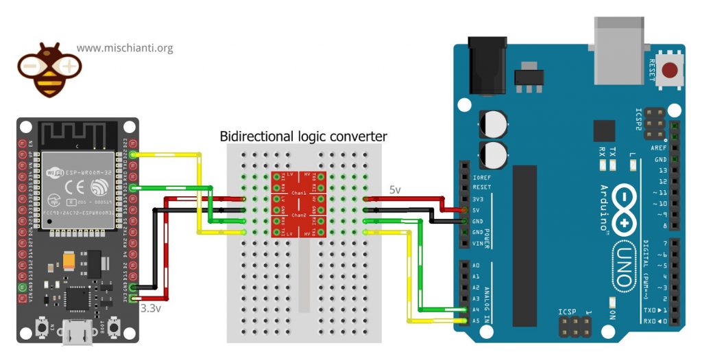
To connect a device with a 5v logic level you can use a bidirectional logic level converter.
You can buy here the logic level converter Aliexpress
here a simple connection schema.
I2C interface, change default pins and add manage additional interface
Default initialization Wire.begin() can be also write
Wire.begin(SDA, SCL, 100000L); // SDA = 21, SCL = 22 and frequences = 100Mhz
you can also use the “extended” version like so
TwoWire wire0 = new TwoWire(0);
[...]
wire0.begin(SDA, SCL, 100000L); // SDA = 21, SCL = 22 and frequences = 100Mhz
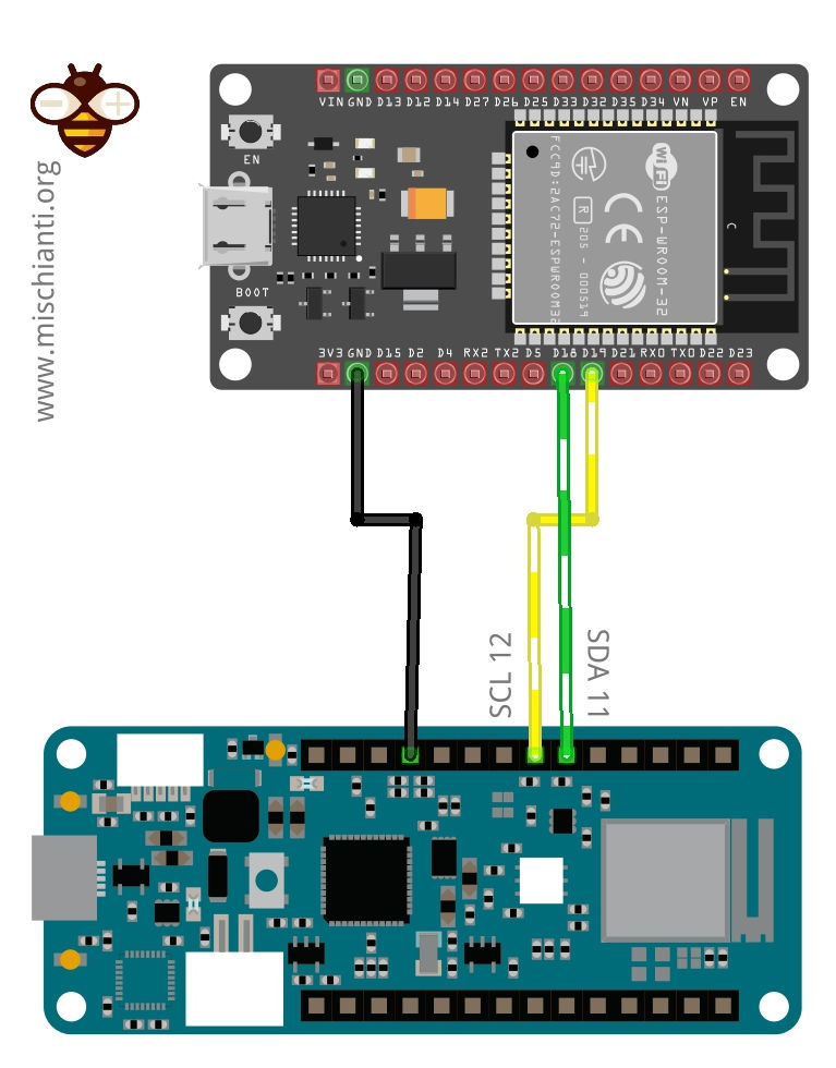
In the same way you can initialize the secondary I2C interface, It’s wrapped by Wire1
Wire1.begin()
or
Wire1.begin(18, 19, 100000L); // SDA = 18, SCL = 19 and frequences = 100Mhz
or you can use the extended declaration with index 1 instead of 0.
TwoWire wire1 = new TwoWire(1);
[...]
wire0.begin(18, 19, 100000L); // SDA = 18, SCL = 19 and frequences = 100Mhz
and the wiring diagram become
Thanks
- ESP32: pinout, specs and Arduino IDE configuration
- ESP32: integrated SPIFFS Filesystem
- ESP32: manage multiple Serial and logging
- ESP32 practical power saving
- ESP32 practical power saving: manage WiFi and CPU
- ESP32 practical power saving: modem and light sleep
- ESP32 practical power saving: deep sleep and hibernation
- ESP32 practical power saving: preserve data, timer and touch wake up
- ESP32 practical power saving: external and ULP wake up
- ESP32 practical power saving: UART and GPIO wake up
- ESP32: integrated LittleFS FileSystem
- ESP32: integrated FFat (Fat/exFAT) FileSystem
- ESP32-wroom-32
- ESP32-CAM
- ESP32: use ethernet w5500 with plain (HTTP) and SSL (HTTPS)
- ESP32: use ethernet enc28j60 with plain (HTTP) and SSL (HTTPS)
- How to use SD card with esp32
- esp32 and esp8266: FAT filesystem on external SPI flash memory
- Firmware and OTA update management
- Firmware management
- OTA update with Arduino IDE
- OTA update with Web Browser
- Self OTA uptate from HTTP server
- Non-standard Firmware update
- Integrating LAN8720 with ESP32 for Ethernet Connectivity with plain (HTTP) and SSL (HTTPS)
- Connecting the EByte E70 to ESP32 c3/s3 devices and a simple sketch example
- ESP32-C3: pinout, specs and Arduino IDE configuration
- Integrating W5500 with ESP32 Using Core 3: Native Ethernet Protocol Support with SSL and Other Features
- Integrating LAN8720 with ESP32 Using Core 3: Native Ethernet Protocol Support with SSL and Other Features
- Dallas ds18b20:
- Guide to I2C on ESP32: Communication with Heterogeneous 5V and 3.3V Devices, Additional Interface Management and Scanner
- Display
- Complete Guide: Using an ILI9341 Display with the TFT_eSPI Library
- Integrating Touch Screen Functionality with Your ILI9341 TFT Display
- SSD1683 eInk Display with GxEPD and ESP32 (and CrowPanel 4.2″ HMI): basics and configuration
- SSD1683 eInk Display with GxEPD and ESP32 (and CrowPanel 4.2″ HMI): fonts, shapes, and images
- ESP32 e Display eInk SSD1683: come realizzare una Semplice Stazione Meteo (anche su CrowPanel 4.2″ HMI) con le API di OpenWeatherMap
- How to Send Emails with Attachments on ESP32/ESP8266 (EMailSender v4.0.0 & STARTTLS)
- ESP32 High Performance FTP Server: A Deep Dive into the MultiFTPServer Library (v3.x)
- HC-SR04 Ultrasonic Sensor with ESP32 and Arduino: Complete Guide
- How to connect multiple HC-SR04 sensors with PCF8574 (3 methods)
- Fix slow HC-SR04 sensors with PCF8574: the hybrid approach trick [Guide]
- i2c Arduino: how to create a network, parameters, and address scanner
- i2c Arduino SAMD MKR: additional interface SERCOM, network, and address scanner
- i2c esp8266: how to, network 5v, 3.3v, speed, and address scanner
- Guide to I2C on ESP32: Communication with Heterogeneous 5V and 3.3V Devices, Additional Interface Management and Scanner