ESP32 practical power saving: manage WiFi and CPU – 1
The ESP32 can activate the energy-saving modes of light sleep and deep sleep, but in many cases, we cannot use such a solution. However, it is still possible to apply some options to the functional units for reducing energy consumption.
You can buy the esp32 from my selection here ESP32 Dev Kit v1 - TTGO T-Display 1.14 ESP32 - NodeMCU V3 V2 ESP8266 - NodeMCU ESP-32S - WeMos Lolin32 - WeMos Lolin32 mini - ESP32-CAM programmer - ESP32-CAM bundle - ESP32-WROOM-32 - ESP32-S - ESP32-WROOM-32 - ESP32 2.8 Inch Touch ESP32-2432S028
In light sleep mode, digital peripherals, most RAM, and CPUs are clock-gated, and supply voltage is reduced. Upon exit from light sleep, peripherals and CPUs resume operation, their internal state is preserved.
In deep sleep mode, CPUs, most of the RAM, and all the digital peripherals clocked from the clock of the Advanced Peripheral Bus (APB_CLK) are powered off. The only parts of the chip which can still be powered on are real-time clock (RTC) controller, RTC peripherals, including Ultra-Low Power (ULP) coprocessor, and RTC memories (slow and fast).
In this table, you can see the table from the datasheet of esp32 with information on how sleep mode is grouped.
| Power mode | Description | Power consumption | ||
Active (RF working) |
Wi-Fi Tx packet |
78 mA ~ 90 mA without communication For TX RX more info in the next table |
||
| Wi-Fi/BT Tx packet | ||||
| Wi-Fi/BT Rx and listening | ||||
Modem-sleep |
The CPU is powered on. |
240 MHz * | Dual-core chip(s) | 30 mA ~ 68 mA |
| Single-core chip(s) | N/A | |||
| 160 MHz * | Dual-core chip(s) | 27 mA ~ 44 mA | ||
| Single-core chip(s) | 27 mA ~ 34 mA | |||
| Normal speed: 80 MHz | Dual-core chip(s) | 20 mA ~ 31 mA | ||
| Single-core chip(s) | 20 mA ~ 25 mA | |||
| Light-sleep | – | 0.8 mA | ||
Deep-sleep |
The ULP co-processor is powered on. | 150 µA 100 µA @1% duty 10 µA | ||
| ULP sensor-monitored pattern | ||||
| RTC timer + RTC memory | ||||
| Hibernation | RTC timer only | 5 µA | ||
| Power off | CHIP_PU is set to low level, the chip is powered off. | 1 µA | ||
How to measure ampere
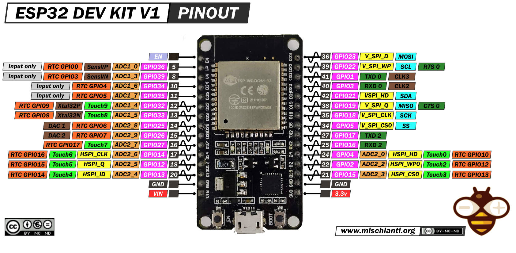
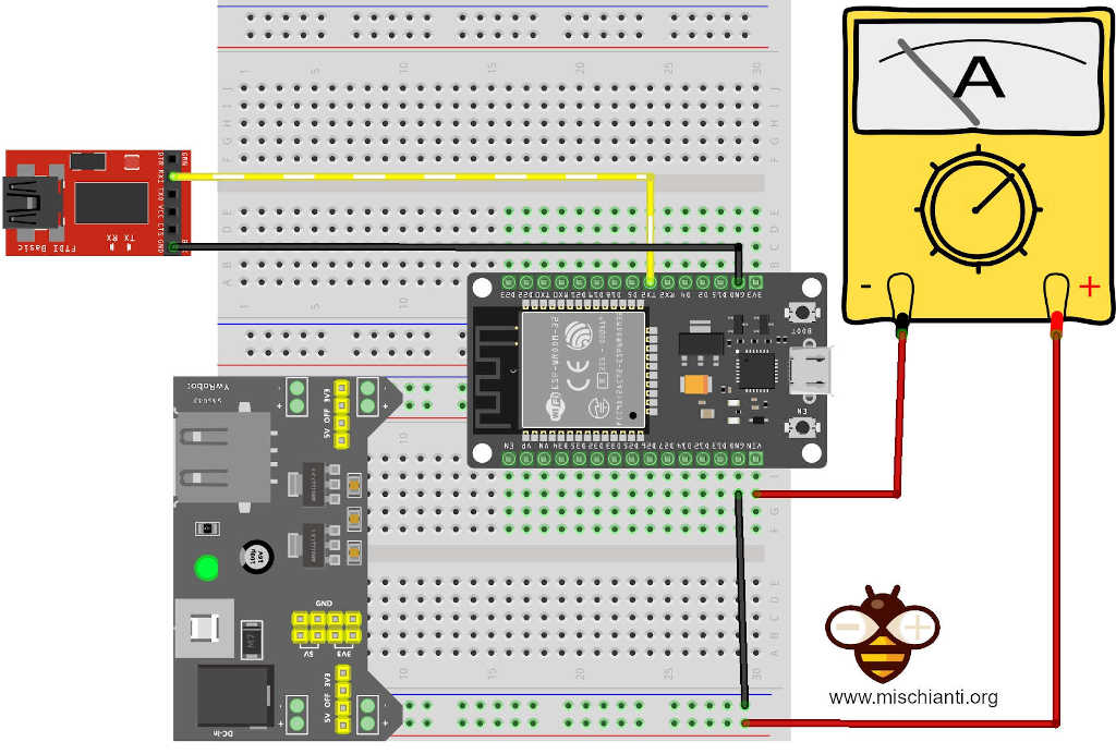
Now we will check how much power consumes the ESP32 in many situations and configurations. Here is the connection schema we used.
Power the esp32 to the 5v pin and GND pin with an external power supply and disconnect the USB. To log, we use the Serial2 port, but if you want to use the Serial port, you must only move the FTDI converter to the TX pin instead TX2 pin. You can’t use USB because it powers the device, and the multimeter gets the wrong amperage.
For the Serial reading, you can refer to this article “ESP32: manage multiple Serial and logging for debugging“.
WiFi management
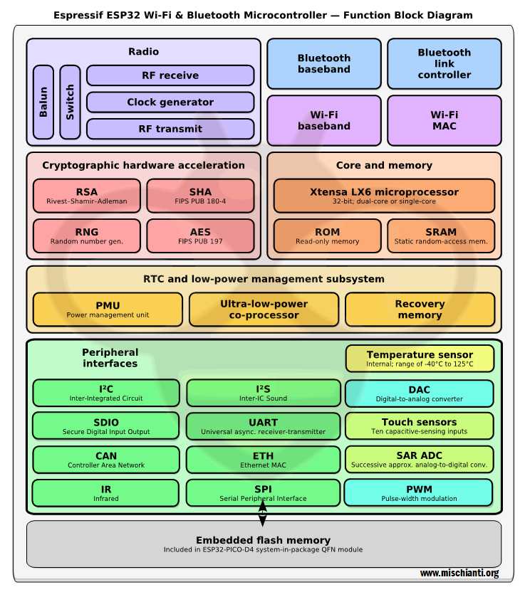
A system to manage battery endurance is to work on a single microcontroller unit. As you see in the upper schema, there are a lot of functional units that you don’t use or can manage.
Reduce communication with WiFi
Turning on WiFi or Bluetooth consumes amps, but it is when they communicate that they consume a lot of power, as you can see in this table:
| Mode | Min | Typ | Max | Unit |
| Transmit 802.11b, DSSS 1 Mbps, POUT = +19.5 dBm | – | 240 | – | mA |
| Transmit 802.11g, OFDM 54 Mbps, POUT = +16 dBm | – | 190 | – | mA |
| Transmit 802.11n, OFDM MCS7, POUT = +14 dBm | – | 180 | – | mA |
| Receive 802.11b/g/n | – | 95 ~ 100 | – | mA |
| Transmit BT/BLE, POUT = 0 dBm | – | 130 | – | mA |
| Receive BT/BLE | – | 95 ~ 100 | – | mA |
So the first thing you can do is reduce the communication time to the minimum possible.
WiFi: enable power saving modes or get best performance
If WiFi connection needs to be maintained, enable WiFi modem sleep, and allow automatic light sleep feature. This will allow the system to wake up from sleep automatically when required by the WiFi driver, thereby maintaining the connection to the AP.
You can manage WiFi power saving management, and there are three possibilities that you can set.
WIFI_PS_NONE: disable modem sleep entirely;WIFI_PS_MIN_MODEM: enable Modem-sleep minimum power save mode;WIFI_PS_MAX_MODEM: to enable Modem-sleep maximum power save mode.
WIFI_PS_MIN_MODEM is the default parameter; when modem sleep is enabled, received WiFi data can be delayed for as long as the DTIM period.
A delivery traffic indication map (DTIM) is a kind of TIM that informs the clients about the presence of buffered multicast/broadcast data on the access point. It is generated within the periodic beacon at a frequency specified by the DTIM Interval. Beacons are packets sent by an access point to synchronize a wireless network. Normal TIMs that are present in every beacon are for signaling the presence of buffered unicast data. After a DTIM, the access point will send the multicast/broadcast data on the channel following the standard channel access rules.
The problem of the DTIM period is that if you have a lot of traffic in your network, you may receive many beacons messages.
WIFI_PS_MAX_MODEM, when modem sleep is enabled, received WiFi data can be delayed for as long as the listen interval duration. This feature is hidden by the default E32 core because there isn’t a significant gain with this technique.
WIFI_PS_NONE disable modem sleep entirely. This has much higher power consumption but provides minimum latency for receiving WiFi data in real-time.
With my esp32 DEV KIT v1, I obtain this power-consuming difference.
| WiFi sleep mode | Power consumption (no send) |
|---|---|
| WIFI_PS_NONE | 145mA |
| WIFI_PS_MIN_MODEM (default) | 80mA ~ 108mA |
| WIFI_PS_MAX_MODEM | 80mA ~ 108mA |
But now we are going to the more exciting part, managing this kind of power savings.
Take this code as an example.
/*
 *  ESP32
 *  Manage WiFi sleep mode
 *  by Mischianti Renzo <https://mischianti.org>
 *
 *  https://mischianti.org
 *
 * You may copy, alter and reuse this code in any way you like, but please leave
 * reference to www.mischianti.org in your comments if you redistribute this code.
 */

#include <WiFi.h>
#include <BluetoothSerial.h>

#define STA_SSID "<YOUR-SSID>"
#define STA_PASS "<YOUR-PASSWD>"

BluetoothSerial SerialBT;

void setWiFiPowerSavingMode();

void setup() {
	Serial2.begin(115200);

	while(!Serial2){delay(500);}

  	SerialBT.begin("ESP32test"); //Bluetooth device name
	SerialBT.println("START BT");

	Serial2.println("START WIFI");
	WiFi.begin(STA_SSID, STA_PASS);

    while (WiFi.status() != WL_CONNECTED) {
        delay(500);
        Serial2.print(".");
    }

    setWiFiPowerSavingMode();

    Serial2.println("");
    Serial2.println("WiFi connected");
    Serial2.println("IP address: ");
    Serial2.println(WiFi.localIP());
}

void loop() {

}

void setWiFiPowerSavingMode(){
    WiFi.setSleep(true);
}
With this code, you are set to default parameter, so you set WIFI_PS_MIN_MODEM; if you remove the line setWiFiPowerSavingMode(); the power consumption remains the same, about 80mA ~ 108mA, the min consumption is when no beacon messages are present (so sleep), the max is when beacon messages arrive.
If you change the function like so
void setWiFiPowerSavingMode(){
    WiFi.setSleep(false);
}
the power consumption changes dramatically and increases to 145mA. With the instruction you have set, WIFI_PS_NONE, there is no latency in your WiFi and increases the packet transfer rate.
As I have already written, the third WIFI_PS_MAX_MODEM mode is “hidden” to enable it. You need to import a new package and use primitive instructions.
#include <esp_wifi.h>
[...]
void setWiFiPowerSavingMode(){
    esp_wifi_set_ps(WIFI_PS_MAX_MODEM);
    //    esp_wifi_set_ps(WIFI_PS_NONE);
    //    esp_wifi_set_ps(WIFI_PS_MIN_MODEM);
}
It seems there isn’t a difference, but the interval of check message becomes less frequently because It checks communications at regular intervals (not when beacon messages arrive). The power consumption remains similar to 80mA ~ 108mA and does not change your battery problems, but it could make a difference in a dynamic network.
Disable WiFi
If you don’t need WiFi, whenever you can stop it with the specified command,
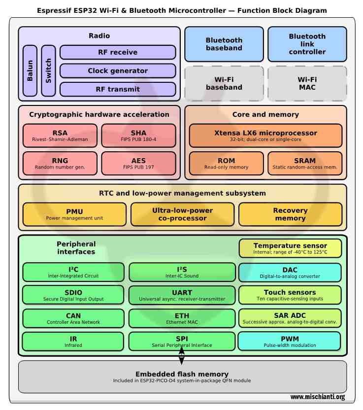
It is also good to disable the ADC; otherwise, you may have problems. The ESP32 integrates two 12-bit SAR (Successive Approximation Register) ADCs supporting a total of 18 measurement channels (analog enabled pins).
The WiFi driver uses ADC2. Therefore the application can only use ADC2 when the WiFi driver has not started.
Here is a simple example.
/*
 *  ESP32
 *  Disable WiFi
 *  by Mischianti Renzo <https://mischianti.org>
 *
 *  https://mischianti.org
 *
 * You may copy, alter and reuse this code in any way you like, but please leave
 * reference to www.mischianti.org in your comments if you redistribute this code.
 */

#include <WiFi.h>
#include <BluetoothSerial.h>
#include <esp_wifi.h>
#include "driver/adc.h"

#define STA_SSID "<YOUR-SSID>"
#define STA_PASS "<YOUR-PASSWD>"

BluetoothSerial SerialBT;

void disableWiFi();

void setup() {
	Serial2.begin(115200);

	while(!Serial2){delay(500);}

  	SerialBT.begin("ESP32test"); //Bluetooth device name
	SerialBT.println("START BT");

	Serial2.println("START WIFI");
	WiFi.begin(STA_SSID, STA_PASS);

    while (WiFi.status() != WL_CONNECTED) {
        delay(500);
        Serial2.print(".");
    }

    Serial2.println("");
    Serial2.println("WiFi connected");
    Serial2.println("IP address: ");
    Serial2.println(WiFi.localIP());

    disableWiFi();
    Serial2.println("WiFi disconnected");
}

void loop() {

}

void disableWiFi(){
        adc_power_off();
	WiFi.disconnect(true);  // Disconnect from the network
	WiFi.mode(WIFI_OFF);    // Switch WiFi off
}
As you can see, the power consumption remains similar, about 72mA (only 8 ~ 12 mA), but the real advantage is when a beacon message arrives, there is no fluctuation in power consumption anymore, so when beacon message travel on the network, the benefit become 18 ~ 46 mA.
To restore WiFi, the function is:
void enableWiFi(){
	adc_power_on();
	WiFi.disconnect(false);  // Reconnect the network
	WiFi.mode(WIFI_STA);    // Switch WiFi off

	Serial2.println("START WIFI");
	WiFi.begin(STA_SSID, STA_PASS);

    while (WiFi.status() != WL_CONNECTED) {
        delay(500);
        Serial2.print(".");
    }

    Serial2.println("");
    Serial2.println("WiFi connected");
    Serial2.println("IP address: ");
    Serial2.println(WiFi.localIP());
}
CPU management
Another critical feature to reduce power consumption is cutting the CPU frequencies.
| CPU freq. | N° Core | Power Consumption |
|---|---|---|
| 240 MHz | Dual-core | 30 mA ~ 68 mA |
| Single-core | N/A | |
| 160 MHz | Dual-core | 27 mA ~ 44 mA |
| Single-core | 27 mA ~ 34 mA | |
| Normal speed: 80 MHz | Dual-core | 20 mA ~ 31 mA |
| Single-core | 20 mA ~ 25 mA |
Exist a simple method to get and set CPU frequencies, getCpuFrequencyMhz() and setCpuFrequencyMhz(80).
The only value admitted (check the table) is 240, 160, and 80, but I tried with lesser value, and It seems. It works correctly (check the video with 40Mhz, 20Mhz, and 10MHz).
Here is a simple example of how to set 80Mhz as a frequency.
/*
 *  ESP32
 *  Manage CPU Frequences
 *  by Mischianti Renzo <https://mischianti.org>
 *
 *  https://mischianti.org
 *
 * You may copy, alter and reuse this code in any way you like, but please leave
 * reference to www.mischianti.org in your comments if you redistribute this code.
 */

#include "Arduino.h"

void setup()
{
	Serial2.begin(115200);

	while (!Serial2){
		delay(500);
	}

	Serial2.print("CPU Freq: ");
	Serial2.println(getCpuFrequencyMhz());

	setCpuFrequencyMhz(80);

	Serial2.print("CPU Freq: ");
	Serial2.println(getCpuFrequencyMhz());
}

void loop()
{

}
I do some tests, as you can see in the video, and I verify that without any management, the consumption is about 66.8mA.
By setting
setCpuFrequencyMhz(160);
is 45.9mA, by setting
setCpuFrequencyMhz(80);
the power become 33.2mA, and with
setCpuFrequencyMhz(40);
è 19.88mA, then I try to set
setCpuFrequencyMhz(20);
the power become 15.43mA with
setCpuFrequencyMhz(10);
and the power becomes 13.19mA.
| Frequency | Power consumption |
|---|---|
| 240Mhz | 66.8mA |
| 160Mhz | 45.9mA |
| 80Mhz | 33.2mA |
| 40Mhz | 19.88mA |
| 20Mhz | 15.43mA |
| 10Mhz | 13.19mA |
Thanks
- ESP32: pinout, specs and Arduino IDE configuration
- ESP32: integrated SPIFFS Filesystem
- ESP32: manage multiple Serial and logging
- ESP32 practical power saving
- ESP32 practical power saving: manage WiFi and CPU
- ESP32 practical power saving: modem and light sleep
- ESP32 practical power saving: deep sleep and hibernation
- ESP32 practical power saving: preserve data, timer and touch wake up
- ESP32 practical power saving: external and ULP wake up
- ESP32 practical power saving: UART and GPIO wake up
- ESP32: integrated LittleFS FileSystem
- ESP32: integrated FFat (Fat/exFAT) FileSystem
- ESP32-wroom-32
- ESP32-CAM
- ESP32: use ethernet w5500 with plain (HTTP) and SSL (HTTPS)
- ESP32: use ethernet enc28j60 with plain (HTTP) and SSL (HTTPS)
- How to use SD card with esp32
- esp32 and esp8266: FAT filesystem on external SPI flash memory
- Firmware and OTA update management
- Firmware management
- OTA update with Arduino IDE
- OTA update with Web Browser
- Self OTA uptate from HTTP server
- Non-standard Firmware update
- Integrating LAN8720 with ESP32 for Ethernet Connectivity with plain (HTTP) and SSL (HTTPS)
- Connecting the EByte E70 to ESP32 c3/s3 devices and a simple sketch example
- ESP32-C3: pinout, specs and Arduino IDE configuration
- Integrating W5500 with ESP32 Using Core 3: Native Ethernet Protocol Support with SSL and Other Features
- Integrating LAN8720 with ESP32 Using Core 3: Native Ethernet Protocol Support with SSL and Other Features
- Dallas ds18b20:
- Guide to I2C on ESP32: Communication with Heterogeneous 5V and 3.3V Devices, Additional Interface Management and Scanner
- Display
- Complete Guide: Using an ILI9341 Display with the TFT_eSPI Library
- Integrating Touch Screen Functionality with Your ILI9341 TFT Display
- SSD1683 eInk Display with GxEPD and ESP32 (and CrowPanel 4.2″ HMI): basics and configuration
- SSD1683 eInk Display with GxEPD and ESP32 (and CrowPanel 4.2″ HMI): fonts, shapes, and images
- ESP32 e Display eInk SSD1683: come realizzare una Semplice Stazione Meteo (anche su CrowPanel 4.2″ HMI) con le API di OpenWeatherMap
- How to Send Emails with Attachments on ESP32/ESP8266 (EMailSender v4.0.0 & STARTTLS)
- ESP32 High Performance FTP Server: A Deep Dive into the MultiFTPServer Library (v3.x)
- Ultra WideBand (Positioning system)
- Reyax RYUW122_Lite (UWB): Pinout, Datasheet, Schema & Specs
- Precision Indoor Positioning (cm) with UWB, ESP32 & Arduino: Hardware & Basics
- UWB Indoor Positioning: Standard Architecture (Anchor & Tag) with RYUW122
- Standalone UWB Positioning: The “IPS” Reverse Architecture (GPS-like) with RYUW122
- HC-SR04 Ultrasonic Sensor with ESP32 and Arduino: Complete Guide
- How to connect multiple HC-SR04 sensors with PCF8574 (3 methods)
- Fix slow HC-SR04 sensors with PCF8574: the hybrid approach trick [Guide]





Thank you for these useful informations.
Please note that adc_power_off() is marked as deprecated. I’m not sure if adc_power_release() is equivalent.
Hi christophe,
thanks for the alert, I will check if there is an equivalent solution.
Thanks again Renzo
Ciao. Vorrei riprodurre quanto hai realizzato per motivi di studio e che trovo molto interessante. Ci sono alcune cose che , però, non ho capito:
1) l’FT232 viene usata per programmare o solo per loggare ?
2) Il cavo che disconnetti nel video è quello dell’ FT232 ?
Grazie anticipate per le risposte
Ciao Cosimo,
in realtà non uso un ft232 ma un CH340G, sono molto simili, la differenza è che quest’ultimo non ha la possibilità di alimentare il microcontrollore. Puoi vedere i 2 modelli qui
ESP32: gestire più seriali e logging per il debug – 3
Quello che stacco è il connettore USB con cui carico lo sketch. Fornisco l’alimentazione, come da schema, direttamente dallo specifico PIN.
Se ti servono altre info scrivo pure.
Ciao Renzo
Ciao Renzo.
Grazie per la risposta.
Quindi, se ho capito bene, tu non usi per nulla l’interfaccia USB integrata nella scheda ma, sia per programmare che per loggare, utilizzi solo ed esclusivamente il CH340G?
Ti faccio questa domanda perchè sto impazzendo tentando di replicare il tuo interessante studio e per questo ho comprato un:
https://www.amazon.it/gp/product/B01N9RZK6I/ref=ppx_yo_dt_b_asin_title_o00_s00?ie=UTF8&psc=1
ma, ogni volta che tento di inviare da IDE un qualunque sketch, anche vuoto, ricevo :
A fatal error occurred: Failed to connect to ESP32: Timed out waiting for packet header
Attualmente alimento la ESP32 a 3,3 V e ho collegato :
RX2 (on ESP32 board) to TX (on FT232RL), and GND to GND.
(Ho provato anche a collegare TX2 (on ESP32 board) to RXI (on FT232RL) ma con lo stesso risultato.
Ho letto, ed impostato, che il jumper sull FT232 dove essere a 3,3 V perchè a 5 V “friggeva tutto”.
Davvero sto impazzendo.
Ciao Cosimo,
no no, mi sono spiegato male:
Uso l’USB per programmare, poi la scollego altrimenti avrei dei dati falsati sugli ampere;
Loggo con il CH340G come nell’esempio che ti ho linkato sopra;
Alimento il microcontrollore da una fonte esterna passando per il tester per verificare gli ampere.
Per programmare un esp32 con un USBtoTTL la procedura è piuttosto fastidiosa, qui ho messo il procedimento con una scheda grezza.
Ciao Renzo
Ok. Tutto chiaro. Ho provato però a fare in questo modo:
1) Carico il codice da IDE alla ESP32 via porta USB (COM3) e tutto funziona.
2) Stacco il cavo USB e quindi la scheda ESP32 si spegne.
3) alimento con un alimentatore a 3,3 V (ma ho provato anche a 5 V) e la ESP32 si riaccende ma non fa più nulla (era configurata come BLE server connessa ad un BLE Client). Questo indipendentemente se ho l’ FT232 collegata oppure no al PC attraverso il cavo mini USB alla COM6.
Ho provato anche a caricare uno dei tuoi sketch ma funzionano solo con l’USB che alimenta la scheda e non quando essa è alimentata esternamente.
Qualche idea?
Non ti so dire Cosimo, se l’alimentazione è sufficiente non dovrebbe esserci differenza tra alimentarlo da USB o da pin.
Ciao Renzo
Sembra un problema piuttosto diffuso. Ho letto questo post:
https://forum.arduino.cc/t/esp32-works-powered-by-usb-but-reboots-from-power-supply/539312.
In realtà io uso un alimentatore molto buono :
https://www.tek.com/en/products/keithley/dc-power-supplies/2220-2230-2231-series
Non so che pesci prendere…
Ma che modello di esp32 usi?
Io onestamente non uso un buon alimentatore, ma problemi di questo tipo non me li ha mai dati.
Ciao Renzo
Questa:
https://www.amazon.it/gp/product/B07VJ34N2Q/ref=ppx_yo_dt_b_asin_title_o07_s00?ie=UTF8&psc=1
E’ la stessa che uso io e non mi ha mai dato problemi di questo tipo.
Prova a verificare che i cavi che portano la corrente siano sufficienti.
Ciao Renzo
Nel video vedo che sul GND lato Vin c’è un condesatore. C’entra qualcosa?
Il condensatore serve a stabilizzare la tensione, ma non dovrebbe essere così rilevante.
Di sicuro aggiungerlo potrebbe aiutare.
Ciao Renzo
Ciao.
Volevo solo dirti che ho risolto il problema.
Era la scheda che funziona se alimentata da USB e non c’è verso di farla funzionare da alimentazione esterna.
Sostituita funziona alla grande sia a 5 che a 3,3 V.
Grazie ancora per il supporto
Hehehe.. era più semplice di come ce lo immaginavamo..
Ciao Renzo
Ciao.
Risolto il problema.
Era la scheda che deve essere difettosa, funziona solo se alimentata da USB.
Sostituita con un’altra scheda identica funziona alla grande sia se alimentata a 5V che a 3,3 V.
Grazie ancora per il supporto
I supposte that the current consumption from esp32 datasheet table is at 3.3V, whilst your current measurements are at 5V. Am I correct? Thank you
Yes, but the regulated power supply drains a very low current. You can see that effect when I compare the battery power devices in the third article.
Bye RM
Agreed, however my question was more about the fact that power = current x voltage therefore you can’t compare directly consumption from esp32 datasheet and your measurements, but you have to multiply by voltage to make comparison.
Ahh! Ok, yes it’s true.
With power the result become farther.
Bye Renzo
Thanks for posting esp32 application, it is very useful for me!
Thanks to you Mike, your feedback is very important for me.
Bye Renzo
Can you please show a working arduino version of
https://github.com/espressif/esp-idf/tree/master/examples/wifi/power_save
I am particularly interested in AP mode. As per https://www.esp32.com/viewtopic.php?f=22&t=12067 one user mentioned as low as 3mA average (though I believe thsi was in station mode). In AP mode, only need it in low power until someone connects to it.
Hi avc2319,
you can find in the article how to activate the WiFi power save mode for esp32 in arduino env with this command
WiFi.setSleep(true);
Bye Renzo