
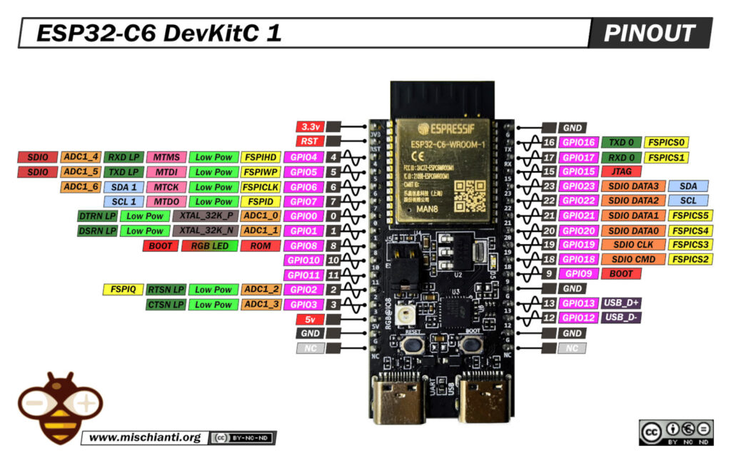
ESP32-C6 DevKitC 1: high-resolution pinout, datasheet, schema and specs
The ESP32-C6 represents a significant evolution in the Espressif product line, moving beyond the high-performance focus of the ESP32-S3 and the cost-optimized ESP32-C3. The ESP32-C6 is a purpose-built connectivity powerhouse that uniquely integrates three key wireless technologies simultaneously.
This “tri-protocol” support is the chip’s defining feature, making it Espressif’s premier solution for the new Matter smart home standard, which relies on a combination of these technologies:
- 2.4 GHz Wi-Fi 6 (802.11ax): This offers higher efficiency, lower latency, and improved performance in congested wireless environments, thanks to features like OFDMA (Orthogonal Frequency-Division Multiple Access) and TWT (Target Wake Time).
- Bluetooth 5 (LE): The chip supports long-range operation via Coded PHY and 2 Mbps high-throughput PHY.
- IEEE 802.15.4 Radio: This is the most significant addition, providing native hardware support for Zigbee and Thread mesh protocols.
The ESP32-C6-DevKitC-1 is the official development board from Espressif designed to showcase this chip. It is built around the ESP32-C6-WROOM-1 module, which packages the ESP32-C6 SoC with a 40 MHz crystal oscillator and, on the common -N8 variant, 8MB of SPI Flash. The board breaks out most of the module’s I/O pins, providing a complete platform for development and prototyping, primarily with the ESP-IDF (Espressif IoT Development Framework).
Here my selection of esp32c6 to buy ESP32-C6-DevKitC-1 8N - ESP32-C6 C3 P4 H2 S3 Super mini
ESP32-C6-DevKitC-1: Hardware Overview and Key Components
The ESP32-C6-DevKitC-1 provides a standard, breadboard-friendly form factor with all essential components for power, programming, and user interaction.
Table of Key Board Components
| Component | Description |
| ESP32-C6-WROOM-1 | The core module containing the ESP32-C6 SoC, 8MB SPI Flash, and an on-board PCB antenna. |
| USB-C to UART Port | The primary port for 5V power, firmware flashing, and serial (UART) communication. It connects via an on-board USB-to-UART bridge chip. |
| ESP32-C6 USB Type-C Port | A native USB port connected directly to the ESP32-C6’s internal USB 2.0 Full Speed (12 Mbps) controller. It is used for native USB applications and JTAG debugging. |
| 5V to 3.3V LDO | A low-dropout power regulator that converts the 5V input from either USB port to the 3.3V operating voltage required by the ESP32-C6 module. |
| BOOT Button | Connected to GPIO9. This button is held down during reset to initiate the Firmware Download (bootloader) mode. |
| RST (Reset) Button | Connected to the chip’s Enable (EN) pin. Pressing this button restarts the system. |
| RGB LED | An addressable (WS2812-type) RGB LED provided for user feedback. It is controlled by GPIO8. |
| J5 Jumper | A two-pin header labeled J5, located above the WROOM-1 module. It is used for precise current measurement. See the detailed section below. |
| 3.3V Power On LED | A static LED (typically red) that illuminates when the board is receiving 3.3V power from the LDO. |
The inclusion of two USB-C ports is a significant feature for advanced development. The “USB-to-UART” port provides a classic and reliable method for programming and serial monitoring. The “ESP32-C6 USB” port connects to the chip’s internal USB Serial/JTAG controller. This enables sophisticated, high-speed debugging using JTAG without requiring an external debugger probe, all while the serial log data streams independently from the other port.
The J5 Current Measurement Jumper
A specific component on the board that often causes questions is the J5 jumper, located directly above the ESP32-C6-WROOM-1 module.
Purpose: The J5 header is an ammeter connection point. It is not a configuration jumper but is specifically designed to allow for precise measurement of the current consumed only by the ESP32-C6-WROOM-1 module, isolating it from the rest of the development board’s circuitry.
How it Works:
This header acts as a bridge in the 3.3V power rail that feeds the WROOM-1 module.
- Default State (Jumper Applied): From the factory, a shunt jumper is placed on J5. This shorts the two pins, completing the 3.3V circuit and allowing the board to function normally.
- Measurement State (Jumper Removed): To measure the module’s precise current consumption (e.g., to verify deep-sleep power figures):
- Power off the board.
- Remove the jumper shunt from the J5 header.
- Connect a multimeter, set to ammeter mode (e.g., mA or uA), in series with the two J5 pins.
- Power the board back on. The multimeter will now display the exact current being drawn only by the ESP32-C6-WROOM-1 module.
This is essential for low-power application development. Other components on the DevKitC-1, such as the USB-to-UART bridge chip, the LDO, and the power LED, all consume a “quiescent current.” Measuring the board’s total current draw from the 5V USB port would give a highly inaccurate and inflated value, making it impossible to validate the microamp-level currents of the ESP32-C6’s deep-sleep modes. J5 provides the necessary isolation for this critical analysis.
Critical Pin Guide: From DevKit to Custom PCB
This guide highlights critical pins on the ESP32-C6. The DevKit (Development Kit) works easily because it has built-in components (like pull-up resistors) that mask these pin requirements.
If you ignore these pin requirements when designing a custom PCB, your board will likely fail to boot or exhibit erratic behavior.
The Strapping Pins
Strapping pins are read at boot-up to set fundamental chip parameters, like the boot mode.
- Key Pins: GPIO 4, 5, 8, 9, 15
- The Problem: If an external circuit (like a sensor or button) pulls one of these pins into the “wrong” state (e.g., LOW) during boot, the chip will not boot normally.
- The Solution: On a custom PCB, if you must use these pins, add an external 10k pull-up resistor to ensure they are HIGH at boot.
Simplified Boot Mode Logic (GPIO 8 & 9)
| GPIO9 (Boot Button) | GPIO8 | Boot Mode | Description |
| HIGH (Released) | HIGH | Normal Flash Boot | (Default) Runs the program from SPI flash. |
| LOW (Pressed) | HIGH | ROM Serial Bootloader | (Download Mode) Waits for new firmware via UART. |
| Other combinations | Invalid Mode | Avoid this. |
The GPIO8 Conflict
This is the most common trap for developers.
- The Problem: GPIO8 has two functions:
- Strapping Pin: It must be HIGH for a normal boot.
- DevKit LED: It controls the on-board RGB LED (WS2812).
- The Trap:
- You build a prototype on the DevKit, and your code uses GPIO8 for the LED. It works.
- You design a custom, cost-optimized PCB and remove the RGB LED.
- FAILURE: Your custom board fails to boot. By removing the LED, you also removed the circuitry that kept GPIO8 HIGH. The pin is now floating or LOW, and the chip cannot boot.
- Recommendation: On any custom PCB, always add an external pull-up resistor to GPIO8 to guarantee a normal boot, even if you are not using it for an LED.
Reserved Pins
These pins are used by the ESP32-C6 module internally.
| Pin Group | GPIOs | Function | Why You Must Not Use Them |
| SPI Flash | GPIO 24-30 | Internal 8MB Flash | Used by the WROOM-1 module. Not available on headers. |
| USB-JTAG | GPIO 12, 13 | Native USB-C Port | Reconfiguring them will disable your USB & JTAG debugging. |
ADC (Analog) Pins
- Pins: GPIO 0-6
- The Problem: The ESP32 ADCs are noisy and non-linear.
- The Cause: Interference from the 2.4GHz Wi-Fi/BLE radio on the same chip.
- Best Practices: Do not expect high precision.
| Improvement | How to Do It |
| Hardware Filter | Add an external 100nF capacitor between the ADC pin and GND. |
| Software Filter | Take multiple samples in your code and average them. |
| High Precision | Use an external ADC chip (like an ADS1115) via I2C. |
Pins “High on Boot”
- The Problem: Some pins (especially strapping pins like GPIO8) are briefly pulled HIGH or output a signal during the chip’s boot-up sequence.
- The Impact: This can cause relays, motors, or LEDs to “twitch,” “click,” or flash when you power on the board.
- The Solution: If this is a problem, add an external pull-down resistor (e.g., 10k) to the pin to keep it safely LOW during boot.
ESP32 C3/C6/S3 Feature Comparison
| Feature | ESP32-C6 (Connectivity) | ESP32-S3 (Performance/AI) | ESP32-C3 (Cost-Optimized) |
| CPU Core | 1x HP RISC-V @ 160 MHz 1x LP RISC-V @ 20 MHz | 2x Xtensa LX7 @ 240 MHz | 1x RISC-V @ 160 MHz |
| SRAM | 512 KB | 512 KB | 400 KB |
| ROM | 320 KB | 384 KB | 384 KB |
| PSRAM Support | Yes (External SPI RAM) | Yes (Octal/Quad SPI) | No |
| AI Acceleration | No | Yes (Vector Instructions) | No |
| Wi-Fi | Wi-Fi 6 (802.11ax) | Wi-Fi 4 (802.11 b/g/n) | Wi-Fi 4 (802.11 b/g/n) |
| Bluetooth | BLE 5.3 | BLE 5.0 | BLE 5.0 |
| Zigbee / Thread | Yes (IEEE 802.15.4) | No | No |
| Native USB | Yes (USB 2.0 Full Speed) | Yes (USB 2.0 OTG) | No (Typically not supported) |
| GPIOs (SoC) | 30 | 45 | 22 |
How to
- ESP32: pinout, specs and Arduino IDE configuration
- ESP32: integrated SPIFFS Filesystem
- ESP32: manage multiple Serial and logging
- ESP32 practical power saving
- ESP32 practical power saving: manage WiFi and CPU
- ESP32 practical power saving: modem and light sleep
- ESP32 practical power saving: deep sleep and hibernation
- ESP32 practical power saving: preserve data, timer and touch wake up
- ESP32 practical power saving: external and ULP wake up
- ESP32 practical power saving: UART and GPIO wake up
- ESP32: integrated LittleFS FileSystem
- ESP32: integrated FFat (Fat/exFAT) FileSystem
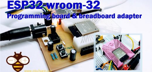
- ESP32-wroom-32
- ESP32-CAM
- ESP32: use ethernet w5500 with plain (HTTP) and SSL (HTTPS)
- ESP32: use ethernet enc28j60 with plain (HTTP) and SSL (HTTPS)
- How to use SD card with esp32
- esp32 and esp8266: FAT filesystem on external SPI flash memory
- Firmware and OTA update management
- Firmware management
- OTA update with Arduino IDE
- OTA update with Web Browser
- Self OTA uptate from HTTP server
- Non-standard Firmware update
- Integrating LAN8720 with ESP32 for Ethernet Connectivity with plain (HTTP) and SSL (HTTPS)
- Connecting the EByte E70 to ESP32 c3/s3 devices and a simple sketch example
- ESP32-C3: pinout, specs and Arduino IDE configuration
- Integrating W5500 with ESP32 Using Core 3: Native Ethernet Protocol Support with SSL and Other Features
- Integrating LAN8720 with ESP32 Using Core 3: Native Ethernet Protocol Support with SSL and Other Features
- Dallas ds18b20:
- Guide to I2C on ESP32: Communication with Heterogeneous 5V and 3.3V Devices, Additional Interface Management and Scanner
- Display
- Complete Guide: Using an ILI9341 Display with the TFT_eSPI Library
- Integrating Touch Screen Functionality with Your ILI9341 TFT Display
- SSD1683 eInk Display with GxEPD and ESP32 (and CrowPanel 4.2″ HMI): basics and configuration
- SSD1683 eInk Display with GxEPD and ESP32 (and CrowPanel 4.2″ HMI): fonts, shapes, and images
- ESP32 e Display eInk SSD1683: come realizzare una Semplice Stazione Meteo (anche su CrowPanel 4.2″ HMI) con le API di OpenWeatherMap
- How to Send Emails with Attachments on ESP32/ESP8266 (EMailSender v4.0.0 & STARTTLS)
- ESP32 High Performance FTP Server: A Deep Dive into the MultiFTPServer Library (v3.x)
- Ultra WideBand (Positioning system)
- Reyax RYUW122_Lite (UWB): Pinout, Datasheet, Schema & Specs
- Precision Indoor Positioning (cm) with UWB, ESP32 & Arduino: Hardware & Basics
- UWB Indoor Positioning: Standard Architecture (Anchor & Tag) with RYUW122
- Standalone UWB Positioning: The “IPS” Reverse Architecture (GPS-like) with RYUW122
- HC-SR04 Ultrasonic Sensor with ESP32 and Arduino: Complete Guide
- How to connect multiple HC-SR04 sensors with PCF8574 (3 methods)
- Fix slow HC-SR04 sensors with PCF8574: the hybrid approach trick [Guide]
Datasheet
ESP32c6 datasheet
Board Schematic
PCB size
Thanks
- Arduino
- esp8285
- esp8266
- ESP32
- DOIT ESP32 DEV KIT v1
- ESP32 DevKitC v4
- ESP32 WeMos LOLIN32
- ESP32 WeMos LOLIN32 Lite
- ESP32 WeMos LOLIN D32
- ESP32-wroom-32
- NodeMCU-32S
- ESP32-S
- ESP32-CAM
- ESP32-2432S028 (Cheap Yellow Display)
- ESP32-2432S032 (Cheap Yellow Display)
- ESP32 s2
- ESP32c3
- ESP32s3
- ESP32c6
- Arduino SAMD
- STM32
- Raspberry Pi


So this chip basically packs Wi-Fi 6, Bluetooth 5.3, and Zigbee 3.0 into one all-in-one IoT chip? Looks like it’s time to upgrade my smart home devices.
___________________________
Driving the future with efficient bldc motor solutions.