
ESP32 DevKitC v4: high resolution pinout, datasheet and specs
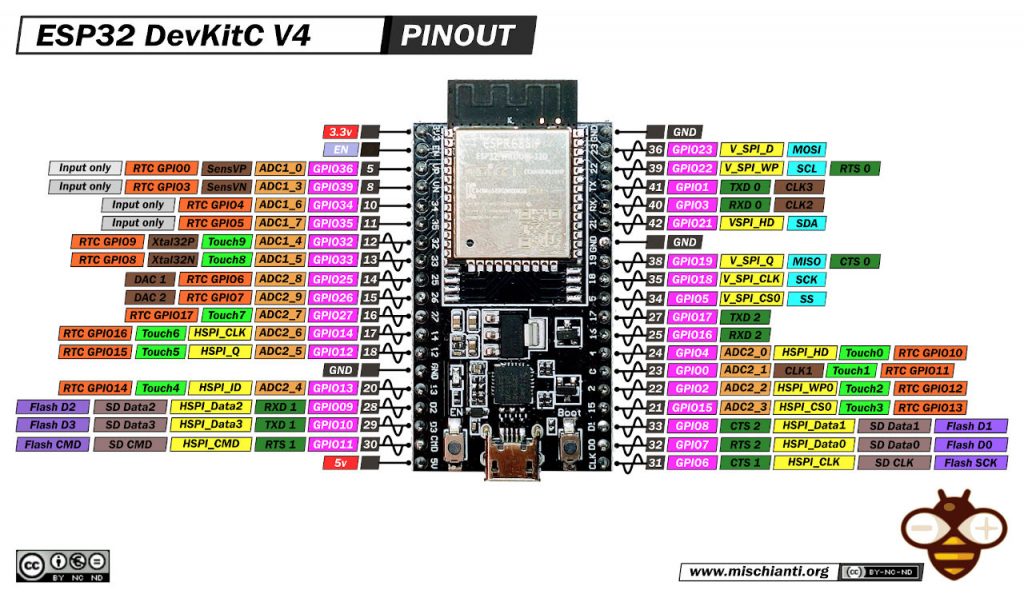
Link to the high resolution pinout image
You can find It here ESP32 Dev Kit v1 - TTGO T-Display 1.14 ESP32 - NodeMCU V3 V2 ESP8266 Lolin32 - NodeMCU ESP-32S - WeMos Lolin32 - WeMos Lolin32 mini - ESP32-CAM programmer - ESP32-CAM bundle - ESP32-WROOM-32 - ESP32-S
- Processors:
- CPU: Xtensa dual-core (or single-core) 32-bit LX6 microprocessor, operating at 160 or 240 MHz and performing at up to 600 DMIPS
- Ultra low power (ULP) co-processor
- Memory: 520 KiB SRAM
- Wireless connectivity:
- Wi-Fi: 802.11 b/g/n
- Bluetooth: v4.2 BR/EDR and BLE (shares the radio with Wi-Fi)
- Peripheral interfaces:
- 12-bit SAR ADC up to 18 channels
- 2 × 8-bit DACs
- 10 × touch sensors (capacitive sensing GPIOs)
- 4 × SPI
- 2 × I²S interfaces
- 2 × I²C interfaces
- 3 × UART
- SD/SDIO/CE-ATA/MMC/eMMC host controller
- SDIO/SPI slave controller
- Ethernet MAC interface with dedicated DMA and IEEE 1588 Precision Time Protocol support
- CAN bus 2.0
- Infrared remote controller (TX/RX, up to 8 channels)
- Motor PWM
- LED PWM (up to 16 channels)
- Hall effect sensor
- Ultra low power analog pre-amplifier
- Security:
- IEEE 802.11 standard security features all supported, including WFA, WPA/WPA2 and WAPI
- Secure boot
- Flash encryption
- 1024-bit OTP, up to 768-bit for customers
- Cryptographic hardware acceleration: AES, SHA-2, RSA, elliptic curve cryptography (ECC), random number generator (RNG)
- Power management:
- Internal low-dropout regulator
- Individual power domain for RTC
- 5μA deep sleep current
- Wake up from GPIO interrupt, timer, ADC measurements, capacitive touch sensor interrupt
How to
- ESP32: pinout, specs and Arduino IDE configuration
- ESP32: integrated SPIFFS Filesystem
- ESP32: manage multiple Serial and logging
- ESP32 practical power saving
- ESP32 practical power saving: manage WiFi and CPU
- ESP32 practical power saving: modem and light sleep
- ESP32 practical power saving: deep sleep and hibernation
- ESP32 practical power saving: preserve data, timer and touch wake up
- ESP32 practical power saving: external and ULP wake up
- ESP32 practical power saving: UART and GPIO wake up
- ESP32: integrated LittleFS FileSystem
- ESP32: integrated FFat (Fat/exFAT) FileSystem
- ESP32-wroom-32
- ESP32-CAM
- ESP32: use ethernet w5500 with plain (HTTP) and SSL (HTTPS)
- ESP32: use ethernet enc28j60 with plain (HTTP) and SSL (HTTPS)
- How to use SD card with esp32
- esp32 and esp8266: FAT filesystem on external SPI flash memory
- Firmware and OTA update management
- Firmware management
- OTA update with Arduino IDE
- OTA update with Web Browser
- Self OTA uptate from HTTP server
- Non-standard Firmware update
- Integrating LAN8720 with ESP32 for Ethernet Connectivity with plain (HTTP) and SSL (HTTPS)
- Connecting the EByte E70 to ESP32 c3/s3 devices and a simple sketch example
- ESP32-C3: pinout, specs and Arduino IDE configuration
- Integrating W5500 with ESP32 Using Core 3: Native Ethernet Protocol Support with SSL and Other Features
- Integrating LAN8720 with ESP32 Using Core 3: Native Ethernet Protocol Support with SSL and Other Features
- Dallas ds18b20:
- Guide to I2C on ESP32: Communication with Heterogeneous 5V and 3.3V Devices, Additional Interface Management and Scanner
- Display
- Complete Guide: Using an ILI9341 Display with the TFT_eSPI Library
- Integrating Touch Screen Functionality with Your ILI9341 TFT Display
- SSD1683 eInk Display with GxEPD and ESP32 (and CrowPanel 4.2″ HMI): basics and configuration
Datasheet
Schema
ESP32
ESP32-WROOM-32
Wiki
Thanks
- Arduino
- esp8285
- esp8266
- ESP32
- DOIT ESP32 DEV KIT v1
- ESP32 DevKitC v4
- ESP32 WeMos LOLIN32
- ESP32 WeMos LOLIN32 Lite
- ESP32 WeMos LOLIN D32
- ESP32-wroom-32
- NodeMCU-32S
- ESP32-S
- ESP32-CAM
- ESP32-2432S028 (Cheap Yellow Display)
- ESP32-2432S032 (Cheap Yellow Display)
- ESP32 s2
- ESP32c3
- ESP32s3
- Arduino SAMD
- STM32
- Raspberry Pi


Hi, could it be that you made a mistake in the pinout picture? It looks to me that GPIO7 and GPIO8 are switched
SCK/CLK* 20 I/O GPIO6, SD_CLK, SPICLK, HS1_CLK, U1CTS
SDO/SD0* 21 I/O GPIO7, SD_DATA0, SPIQ, HS1_DATA0, U2RTS
SDI/SD1* 22 I/O GPIO8, SD_DATA1, SPID, HS1_DATA1, U2CTS
the formating in my last post was a little bit confusing. It is stated in the datasheet:
GPIO6=SD_CLK, GPIO7=SD_DATA0, GPIO8=SD_DATA1
Thanks a lot Felix,
I invert GPIO7 and GPIO8 only label, Data0 Data1 and RTS and CTS are correct i think.
Thanks again Renzo
HI there. Thanks for the daa sheet, but I got really confused when I clicked on the pinout image, as the big pop-out version which is displayed is for a Dev Kit V1, whereas the smaller image on this page is for a Dev Kit V4 (which is what I was looking for!).
Thanks I fixed It.